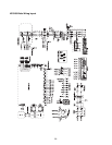
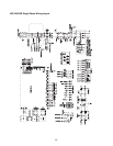
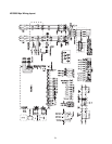
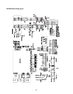
Humidifier runs continuously, %RH is well under set-point.
1. Verify humidistat/RH sensor is wired correctly and dip switches (S2 & S3, See Fig. 10-1, 11-1
and 11-1) on the PC board are set correctly for the humidistat signal.
2. Check humidistat demand signal at low voltage terminal strip. It should be close or at 100%.
3. If humidifier is a three phase model, verify all three phases of power are present and equal.
4. Check amperage draw on all high voltage power lines with a clamp on amp meter. They should be
same or very close to amperage rating on the humidifier's nameplate if the humidistat demand is
100%.
5. Turn off power. Disconnect heating elements and check resistances - see Tables on Pages 35 and
37. If an open circuit or abnormally high resistance is measured, the heating element(s) is
defective. Also, check to see if heating element leads have shorted to ground.
6. If heating elements are OK, check voltages at secondary side of the power module and contactor.
If no or low voltage, check primary fusing.
7. If fuses are OK, check voltage to contactor coil.
(a) If voltage is 24-28VAC at contactor coil, check coil resistance. It should be approximately
8Ω? with wires disconnected. If resistance is OK, check voltage drops across the contactor.
(b) If no voltage to contactor coil, check continuity of wires from PC board to contactor. If
continuity is OK, PC board is likely defective.
8. Check voltage signal to power module. The voltage across TAB8-1 and TAB8-2 (low voltage signal
to power module) should be 12 Vdc at 100% power.
(a) If no or low voltage, the PC board is likely defective.
(b) If voltage is OK, but green "LOAD" LED on the power module is not on, power module is
defective.
9. If green "SIGNAL" LED on power module is on, check voltage drops across power module.
10. If supply voltage and amperage draws are correct and elements appear OK, unit is probably
undersized (not enough capacity for the application). Check sizing or consult factory.
Humidifier does not drain when manual drain.
1. Disconnect and check resistance of drain valve coil. Resistance should be approximately
10Ω (8.3Ω HC-6500/6700).
2. Make sure drain line is pitched and sized correctly. Check for blockage or obstructions in the drain
line. An air gap or funnel must be used as described in Drain Line Section. - See Figure 8-3.
3. If humidifier does not drain at specified interval or when service is to be performed and drain
valve and piping appear OK, there is blockage of the tank drain screen or the PC board may be
defective.
25


