


9
B023
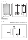
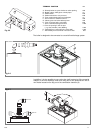
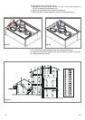
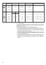
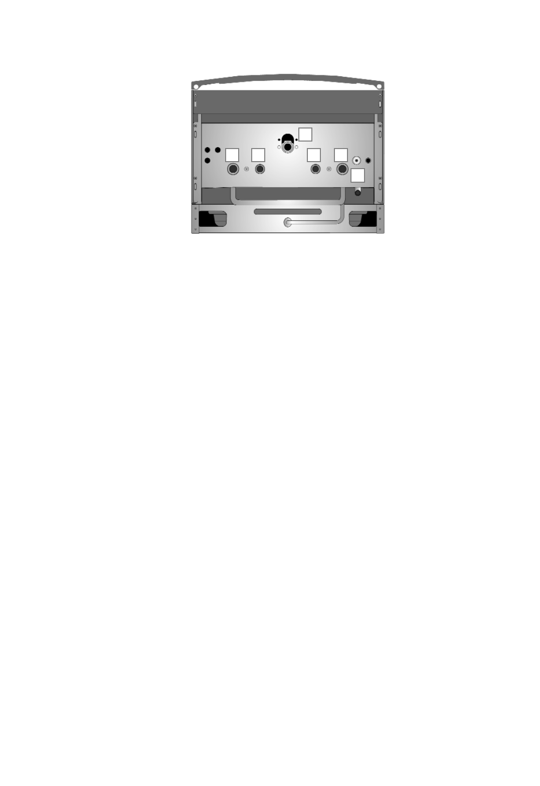
2.9 Water Connections
Legend
A = Central Heating Flow
B = Domestic Hot Water Outlet
C = Gas Inlet
D = Domestic Cold Water Inlet
E = Central Heating Return
I = Safety Valve
Central Heating
Detailed recommendations are given in BS 6798:1987 and BS 5449-1:1990,
the following notes are given for general guidance.
Pipe Work:
Copper tubing to BS EN 1057:1996 is recommended for water pipes. Jointing
should be either with capillary soldered or compression fittings.
Where possible pipes should have a gradient to ensure air is carried naturally
to air release points and water flows naturally to drain taps.
The appliance has a built-in automatic air release valve, however it should be
ensured as far as possible that the appliance heat exchanger is not a natural
collecting point for air.
Except where providing useful heat, pipes should be insulated to prevent heat
loss and avoid freezing.
Particular attention should be paid to pipes passing through ventilated spaces
in roofs and under floors.
By-pass:
The appliance includes an automatic by-pass valve, which protects the main
heat exchanger in case of reduced or interrupted water circulation through
the heating system, due to the closing of thermostatic valves or cock-type
valves within the system.
System Design:
This boiler is suitable only for sealed systems.
Drain Cocks:
These must be located in accessible positions to permit the draining of the
whole system. The taps must be at least 15mm nominal size and
manufactured in accordance with BS 2870:1980.
Safety Valve Discharge:
The discharge should terminate facing downwards on the exterior of the
building in a position where discharging (possibly boiling water & steam) will
not create danger or nuisance, but in an easily visible position, and not cause
damage to electrical components and wiring.
The discharge must not be over an entrance or a window or any other type of
A
C
B D E
I
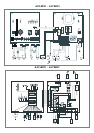
A/23 MFFI - A/27 MFFI
Fig. 2.4