


15
B023
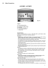
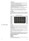
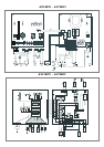
2.11 Electrical Diagram
Legend:
AT = High Voltage P.C.B.
BT = Low Voltage P.C.B.
B = Flame Failure L.E.D.
C = Insufficient Water Pressure L.E.D.
D = Water Temperature Indicator L.E.D.s
E = Overheat Thermostat Warning L.E.D.
F = System Reset Button
G = Selector Knob for Operating Mode
H = Domestic Hot Water Temp. Adjustment
I = Central Heating Temp. Adjustment
J = Wire Connector for Room Thermostat
K = Connector for Total Check System
M = Anti-cycling Device Adjustment for Heating
N = Soft-light Adjustment
O = Max Heating Temperature Adjustment
P = Time Clock Connection
Q = On/Off L.E.D.
R = On/Off Switch
S = Interface Wire for P.C.B.s
T = Relay Motorised Valve
U = Ignitor Relay
V = Gas Valve Relay
W = Fan Relay
X = Circulation Pump Relay
Aa = Adaptor (British Gas use only)
Y = Selector TCS2
A01 = Air Pressure Switch
A02 = Fan
A03 = Gas Valve
A04 = Ignitor
A05 = Motorised Valve
A06 = Circulation Pump
A07 = Flame Detector
A08 = Earth Terminal
A09 = Flame Detection Circuit
A10 = Flame Indicator L.E.D.
A11 = Transformer
A12 = Filter
B01 = Over Heat Thermostat
B02 = Room Thermostat
B03 = Gas Valve Modulator
B05 = Heating Sensor
B06 = Pressure Switch for Heating Circuit
B07 = Microswitch for Diverter Valve
Colours
Gry = Grey
Rd = Red
Bl = Blue
Grn/Yll = Yellow/Green
Wh = White
Brn = Brown
Blk = Black
Wh/Rd = White/Red