


26
installation
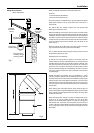
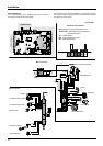
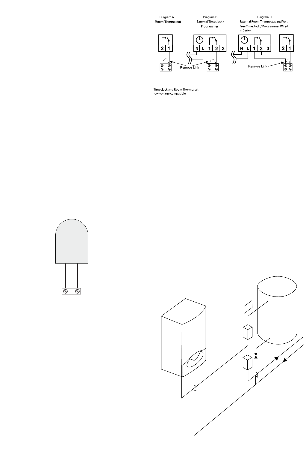
Room Thermostat / Remote Clock Connection
To connect a room thermostat, it is necessary to:
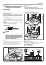
1. Open the control panel
2. Loosen the cable clamp using a screwdriver and insert the wires
leading from the room thermostat
3. Connect the wires to the terminals as indicated in the gure
below, removing the link
4. If a remote time clock is to be tted, using a volt free switching
time clock connect the switching wires from the time clock
following points 1 - 3 above
5. If using an external time clock and room thermostat, these must
be connected in series as shown in diagram C,
6. Ensure that they are well connected and not subject to stress
when the control panel is closed
DO NOT CONNECT 240V TO ANY PERIPHERAL CONNECTIONS
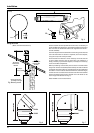
Outdoor sensor connection
- Introduce the outdoor sensor wires
- Loosen the cable clamp using a screwdriver and insert the
wires leading from the outdoor sensor one at a time.
- Connect the wires to the terminals as indicated in the gure
below;
- Make sure that they are well connected and that they are not
subject to stress when the control panel lid is opened or closed;
- Close the ap again, then replace the control panel cover and
the front casing.
- Refer to page 39 for setting the parameters when using the
outdoor sensor.
N
OTE: WHEN CONNECTING THE BOILER TO EXTERNAL CONTROLS, DO
NOT RUN 240V CABLES AND CABLES FOR SWITCHING CIRCUITS
(
WHICH ARE LOW VOLTAGE) TOGETHER, USE SEPERATE CABLES TO
PREVENT INDUCED VOLTAGE ON THE LOW VOLTAGE CIRCUITS.
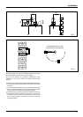
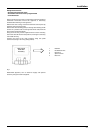
Connector SE on PCB
Outdoor Sensor
Connector TA on PCB
(low voltage switching)
Connector TA on PCB
(low voltage switching)
Connector TA on PCB
(low voltage switching)
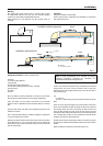
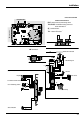
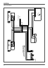
Cylinder connection (CLAS HE EVO SYSTEM)
The boiler can be connected to a central heating system that
uses two zone valves to allow connection to an indirect storage
cylinder.
There are two wiring diagrams shown, one for the connection to
an Unvented Cylinder and one for connection to an open vented
cylinder.
In both cases the boiler connection is shown as TA1.
When connecting the boiler to an external cylinder do not run
240V cables and the cables for the TA1 together, use separate
cables to prevent induced voltage on the low voltage switching
circuit.
NOTE: THE USE OF A ‘Y’ PLAN SYSTEM IS NOT POSSIBLE WITH THE CLAS
HE SYSTEM BOILER DUE TO THE LOW VOLTAGE SWITCHING OF THE APPLIANCE
UNLESS SUITABLE RELAY CONTROLS ARE USED.
Important!!
Ensure that a balancing valve is tted on the cylinder return
and balanced correctly at commissioning stage.
(see p.25)