


25
installation
WARNING
Before performing any work on the boiler, rst
disconnect it from the electrical power supply using
the external bipolar switch and remove the fuse.
Electrical connections
For increased safety, ask a quali ed technician to perform a
thorough check of the electrical system.
The manufacturer is not responsible for any damage caused by
the lack of a suitable earthing system or by the malfunctioning of
the electricity mains supply.
Make sure that the system is able to withstand the maximum
power absorbed by the boiler (this is indicated on the appliance
data plate). Check that the section of the wires is suitable and is
not less 0,75 mm
2
The appliance must be connected to an e ecient earthing system
if it is to operate correctly.
The power supply cable must be connected to a 230V-50Hz
network, where the L-N poles and the earth connection are all
respected.
Important!
In the event that the power supply cable must be changed,
replace it with one with the same speci cations.
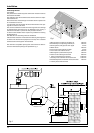
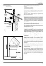
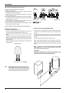
Power supply cable
Important!
The appliance is supplied with a y-lead already
connected, this must be connected to a 240V supply
fused at 3 Amp and must facilitate completed
electrical isolation of the appliance, by use of a fused
double pole isolator having a contact separation of at
least 3mm in all poles or alternatively by means of a 3A
fused three pin plug and unswitched shuttered socket
outlet both complying with BS1363.
The use of multiplugs, extension leads or adaptors is strictly
prohibited.
It is strictly forbidden to use the piping from the hydraulic, heating
and gas systems for the appliance earthing connection.
The boiler is not protected against the e ects caused by lightning.
If the mains fuses need to be replaced, use 2A rapid fuses.
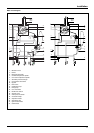
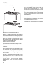
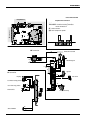
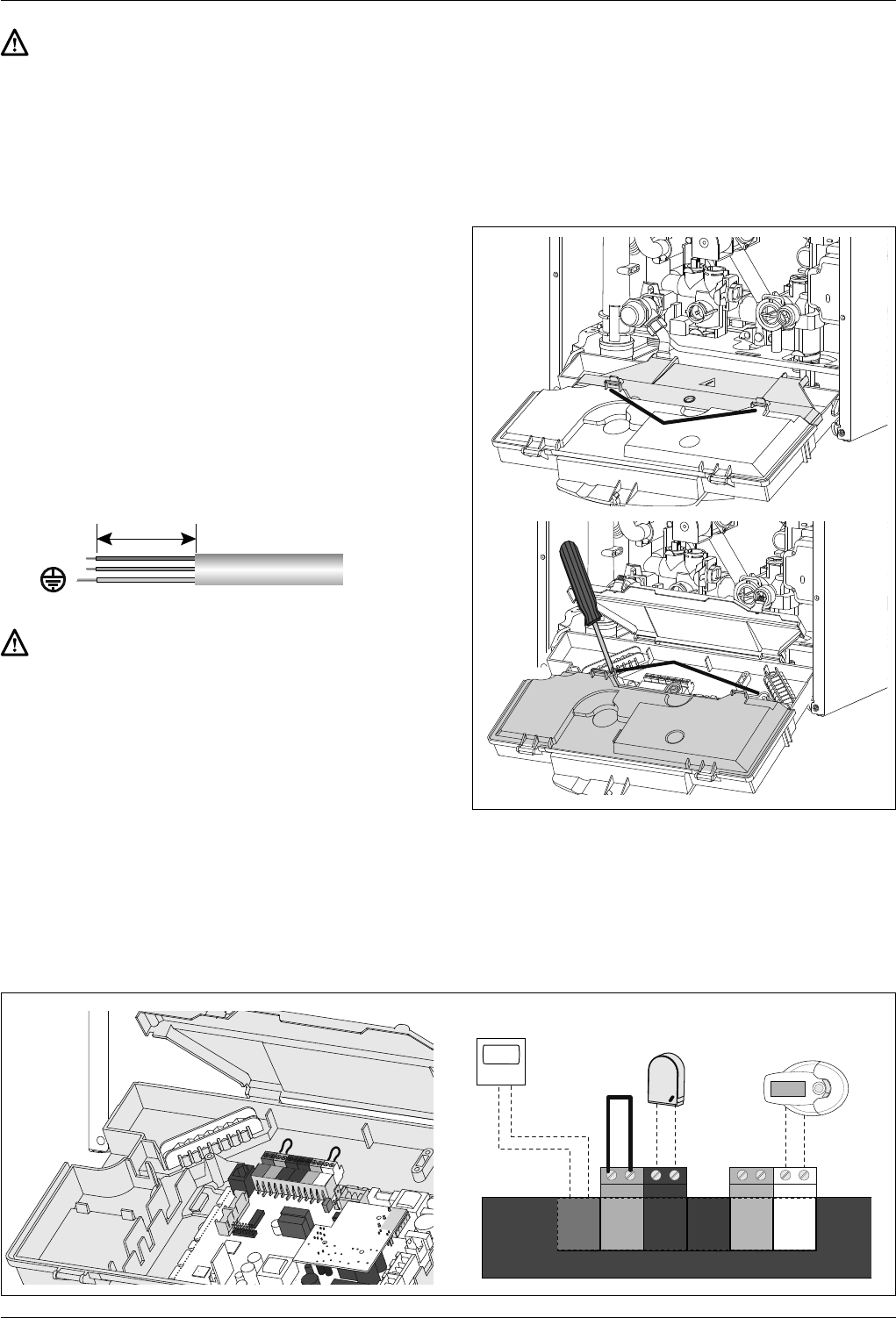
Peripheral unit connection
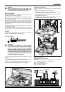
To access peripheral unit connections carry out the following
steps:
- Disconnect the boiler from the power supply
- Remove the casing by unhooking it from the instrument panel
- Rotate the control panel while pulling it forwards
- Unhook the two clips “a”, rotate the cover “b” to have access to
the peripherical connections
- Unscrew the two screws “c” and remove the cover “d” of the
instrument panel to have access to the main P.C.B.
H05V2V2-F
60
N
L
a
b
c
d
BUS
T
B
TA2
SE
TNK
SOL TA1
BUS
TB
TA2
FLOOR
SETNK SOL TA1
CN1
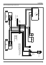
R
emote Control
Outdoor sensor
Underoor heating
thermostat
Room Thermostat 2
Room Thermostat 1
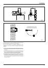
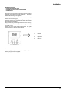
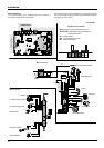
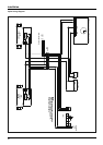
Peripheral connections:
BUS = Remote control connection
FLOOR/TA2 = the under oor heating thermostat or the room
thermostat 2 (selected via parameter 223)
SE = the external sensor.
SOL = Solar temperature probe
TA1 = the room thermostat 1