


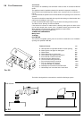
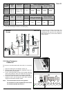
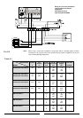
L = Sum of the total length of exhaust + air intake piping.
10
Exhaust
Type
C12 (xx)
C32 (xx)
C42 (xx)
Restrictor
ø 41 mm
L min = 0.5 m
L max = 1 m
Maximum
Extension
Exhaust/Air
L = 5 m
Risk of Condensation Forming
Coaxial
Systems
ø 60/100
Piping not insulated
ø 41
restrictor NO restrictor
NONE NONE
Piping insulated
ø 41
restrictor NO restrictor
NONE NONE
TABLE 2.1
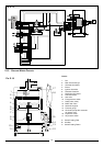
15 RFFI
Exhaust
Type
C12 (xy)
C32 (xy)
C42 (xy)
Restrictor
ø 41 mm
L max = 30 m
Maximum
Extension
Exhaust/Air
78 m
Risk of Condensation Forming
Twin Pipe
Systems
ø 80/80
Piping not insulated
ø 41
restrictor NO restrictor
1.2 m 2.5 m
Piping insulated
ø 41
restrictor NO restrictor
8 m 11.0 m
15 RFFI
T
WIN PIPE
SYSTEMS
FIG. 2.10
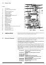
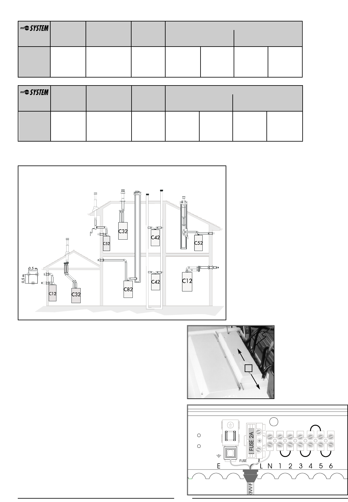
In calculating the lengths of the pipes, the
maximum length “L” must also take into
consideration the values for the exhaust/air
intake end terminals, as well as 90° elbows for
coaxial systems.
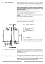
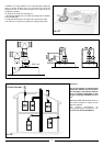
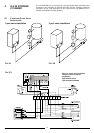
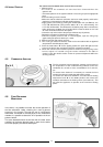
To connect a room thermostat and/or time clock, it is necessary
to:
1. - Open the control panel as indicated in section 4.3;
2.- Remove screws “A” and remove the inspection cover from
the reverse of the control panel;
3. - For the room-thermostat connect the thermostat switching
wires to the position 5 and 6 and remove the wire link (for
three-wire thermostats connect the neutral to terminal N);
4. - For the time clock connect the clock switching wires to the
positions 3 and 4 and connect the clock motor electrical
supply to the terminals marked L and N.
Note: A frost thermostat is built-in to the appliance.
For connection to control systems with zone valves
for hot water cylinders see section 3.
2.10 ROOM THERMOSTAT
C
ONNECTION
A