96 720 606 446
WARNING
Note: The burners of an instantaneous “on demand” water
heater such as the AquaStar are only on at the time that
hot water is actually being used, the vent pipe is therefore
cold except for the short durations when hot water is being
used, it is therefore very important that the venting and air
supply be adequate to provide a good positive draft as soon
as the burners turn on.
The AquaStar 38B instantaneous water heaters have built-
in draft diverters and are designed for indoor installation
only. The draft diverter outlet must be connected to an
unobstructed vent of the same size, or larger.
In Canada, CAN/CGA-B149 Installation Code for detailed
requirements
In U.S.A., ANSI Z223.1 - NFPA 54, National Fuel Gas
Code for detailed requirements.
To check the draft:
Close all doors and windows to the outside.
Turn on all appliances that force air out of the building.
These include all exhaust/ventilation fans, furnaces, clothes
dryers, wood burning stoves, etc.
Open all doors between the AquaStar and these other
appliances.
Run the unit for at least 10 minutes. Then hold an ordinary
mirror at the side above the front shell. Any flue gases
backdrafting will cause the mirror to fog. This is a serious
health hazard and must be corrected. Poor venting can result
in soot building up inside the heater, overheating of the heater
and freezing of the heat exchanger in a freezing environment.
The mirror will remain clear with a properly functioning draft.
GAS CONNECTIONS
and Gas Regulator
Before connecting the gas supply, check the rating plate on
the right side of the front cover to be sure that the heater is
rated for the same gas to which it will be connected.
In the United States: The installation must conform with
local codes or, in the absence of local codes, the National
Fuel Gas Code ANSI Z223.1/NFPA 54.
In Canada: The Installation should conform with CGA B149
INSTALLATION CODES and /or local installation codes.
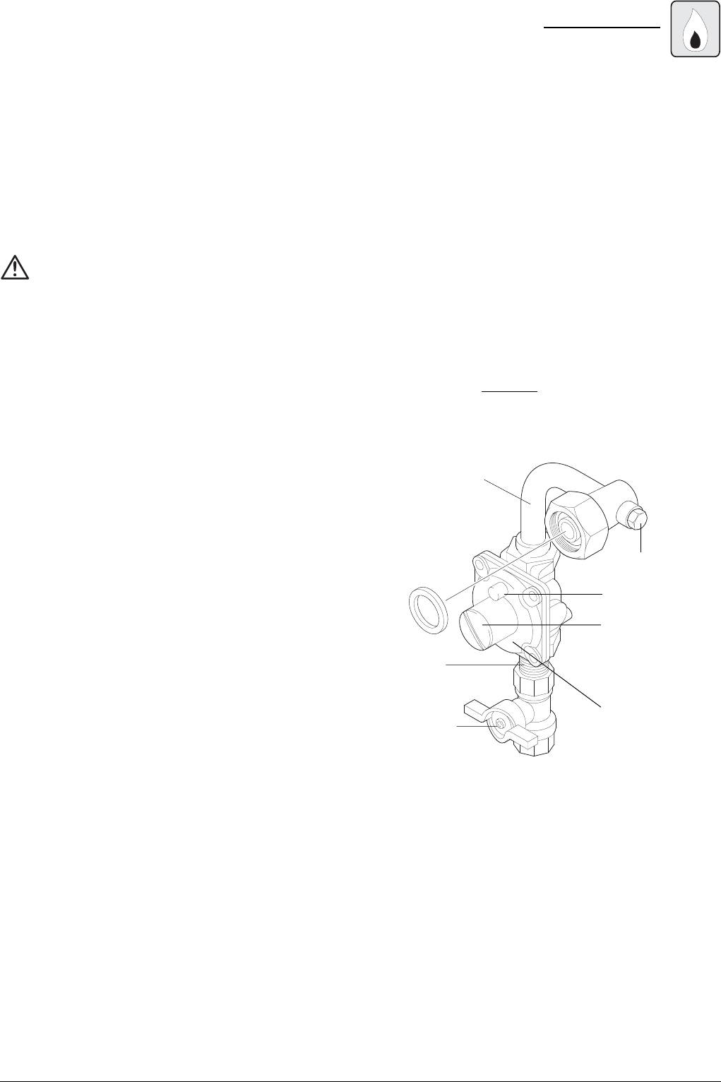
NOTE: The Aquastar 38 B is supplied with a gas pressure
regulator that must be installed on the heater before
attaching the gas supply line. See figure 2. Place the gas
regulator between the gas supply connection (which
comes with a manual shutoff valve) and the gas fitting
wich is connected to the heater’s gas inlet. There is a
pressure tap on this gas fitting. The regulator supplied
with the heater is preset for the gas shown on the rating
plate to the correct pressure. It is an appliance level
regulator designed for low inlet pressure (less than 1/2
Psig or 15” W.C.) DO NOT connect to an unregulated or
high pressure propane line or to a high pressure
commercial natural gas line.
Fig. 2 - Gas Pressure Regulator
APPLIANCE GAS
REGULATOR
1/2” BRASS
BUSHING
GAS SHUT-OFF
COCK
INLET GAS FITTTING
WITH GASKET
PLASTIC VENT CAP
PRESSURE
REGULATOR
(with directional
arrow on reverse
side pointing upward)
PRESSURE TAP
The pressure regulator provided with the heater is adjusted
to deliver the proper gas pressure (as indicated on the rating
plate and in the manual for altitude up to 2000 feet (660
meters) above sea level. On appliances being installed above
2000 ft (660 meters) elevation, the inlet gas pressure should
be set at installation to the value shown below.
NOTE: The gas pressures specified below refer to
pressures taken at the pressure tap on the gas inlet pipe
just above the regulator (See Fig 2). These readings
should be taken while the heater is operating at full input
— i.e. maximum water flow with the temperature dial
selector turned all the way clockwise.


