


10 6 720 606 446
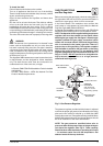
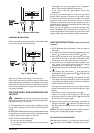
Connecting the pressure relief valve (PRV)
A listed pressure relief valve supplied with the heater must
be installed at the time of installation. Should a discharge
line be added to the PRV no valve is to be placed between
the PRV and the heater. No reducing coupling or other
restriction may be installed in the discharge line. The
discharge line must be installed such that it allows complete
drainage of both the PRV and the line. The location of the
PRV must be readily accessible for servicing or replacement.,
and be mounted as close to the water heater as possible
See Fig 4. To install the PRV, a suitable fitting connected to
an extension on a “T” fitting can be sweated to the hot
water line.
National Fuel Gas Code requires that a sediment trap (drip
leg) be installed on gas appliances not so equipped. The
drip leg must be accessible and not subject to freezing
conditions. Install in accordance with the recommendations
of the serving gas supplier.
WARNING: The heater and its individual shutoff
valve must be disconnected from the gas supply piping
system during any pressure testing of that system at
test pressures in excess of 0.5 psig.
The water heater must be isolated from the gas supply piping
system by closing the manual shutoff valve during any
pressure testing of the gas supply piping system at test
pressures equal to or more than 0.5 psig.
The water heater, including the pressure regulator provided
with it, must not be operated at gas supply pressures in
excess of 0.5 psig. If overpressure has occurred, such as
through improper testing of the gas lines or malfunction of
the supply system, the gas valve and regulator must be
checked for safe operation.
Make sure that the regulator vent is protected against
blockage.
When your connections are made, check for gas leaks at
all joints (not just the ones you made). Apply some soapy
water to all gas fittings and gas valve. Soap bubbles are a
sign of a leak.
NOTE: Do not apply soap solution to pilot filter screen or
pilot orifice area. If you have a leak, shut off the gas. After
verifying that required gaskets are in place, tighten
appropriate fittings to stop leak. Turn the gas on and check
again with a soapy solution. Never test for gas leaks using
a match or flame.
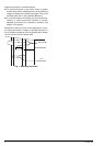
MAXIMUM INLET GAS FLOW PRESSURE SETTING
Above 4.500 ft consult your local gas supplier.
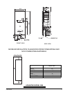
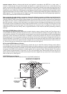
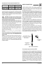
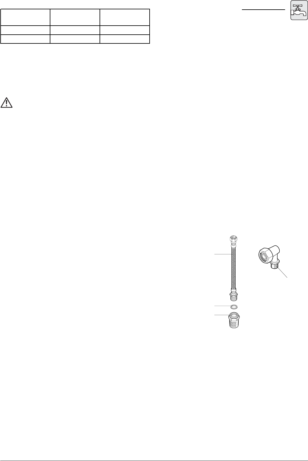
Fig. 3 - Water connections
HOT OUTLET LINE
(CONNECTED TO HEAT
EXCHANGER)
3/8” WASHER
3/8” x 1/2”
BRASS FITTING
COLD WATER
INLET
WATER CONNECTIONS
Install the heater centrally in the building if possible and
make hot water piping runs as short as possible When facing
the heater, the cold water inlet will be on the right and the
hot water outlet on the left.
Although water piping throughout the building may be other
than copper, copper or galvanized piping should be used
when connecting to the heaters ½” male NPT connectors
(follow local codes if more stringent). Plastics or other PEX
type plumbing line materials are not suitable for connecting
directly to the water heater. Keep water inlet pipe to no less
than ½” (19.05mm) diameter to allow the full flow capacity.
If the cold and hot connections to the heater are reversed,
the heater will not function.
The 38B is provided with one rigid elbow connector that
must be connected to the cold inlet fitting of the brass water
valve, no pipe dope or thread tape is to be used at this joint.
The outlet flexible connector is supplied attached to the
heat exchanger, the supplied 3/8” washer and 3/8”x1/2”
brass fitting should be attached to it to allow a ½” NPT
connection to be made. See Fig. 3.
Be certain there are no loose particles or dirt in the piping.
Blow out or flush the lines before connecting to the water
heater. Full port valves should be installed on both the cold
water supply and hot water outlet lines to facilitate servicing
the heater. For installation on a private well system with the
use of a pressure tank, the lowest pressure range setting
recommended is 30-50 psi (2.07-3.45 bar).
Altitude Natural Gas Liquid Propan
e
inches W.C: inches W.C:
0' - 2.000 ft 5.7" 10.5"
2.000 ft - 4.500 ft 4.6" 8.4"