


35
Major Components
♦ Defrost Controller: Monitors condition (open or closed) of binary outdoor coil defrost temperature
sensor (DTS). The controller accumulates compressor run time where conditions are conducive to ice
formation. Upon an accumulation of a predetermined period of “ice forming” run time, controller
initiates a defrost cycle by supplying control voltage through the DTS, energizing the coil of control relay
#1 (CR-1); in turn, CR-1 energizes the refrigerant circuit reversing valve (and stops fan operation),
sending hot refrigerant vapor to the outdoor coil. (When the DTS warms, the DTS contacts open, de-
energizing the refrigerant reversing valve and–if a call for heat is present–re-starting the fan motor.)
♦
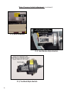
Defrost Temperature Sensor (DTS): Normally-open SPST switch that attaches to a return loop of the
evaporator (outdoor) refrigerant coil. The DTS senses evaporator coil temperature, and sensor
contacts close on a fall in temperature. Specifications: Close @ 25°F, Open @ 55°F (+- 9°F).
♦ Control Relay #1 (CR-1): 3-pole, double-throw relay, equipped with a 24-volt control coil. Upon an
accumulation of sufficient “icing run time” this relay receives a 24-volt signal from the defrost controller,
through the DTS. When CR-1’s coil is energized, the refrigerant reversing valve is energized; the fan
relay is de-energized; the defrost light is illuminated, and the defrost controller reset circuit (RST) is
opened.
♦ Fan Relay: DPDT relay, used in a SPST capacity; relay is equipped with a 24-volt control coil. During
normal heating (non-defrost) operation, the control coil is energized and electrical power for the fan
motor is provided through the closed terminals of this relay. Upon a call for defrost, CR-1 interrupts
control voltage to the fan relay. With Fan relay “open”, fan operation ceases.
♦ Refrigerant Reversing Valve (RRV): Mechanical, 24-volt, pilot operated electric solenoid valve. During
heating mode, the RRV control coil is de-energized. Upon a call for defrost, the RRV control coil is
energized through CR-1. Now energized, the RRV diverts hot refrigerant vapor to the outdoor
refrigerant air coil, and defrost is accomplished.
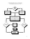
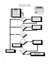
Sequence of Operation
1. Start... Normal Heating Cycle in Operation: evaporator temperature above 25°F;
2. Evaporator temperature falls to 25°F; DTS closes, and the defrost controller begins accumulating “ice
forming” run time. Run time accumulates only when the compressor is operating.
3. With DTS remaining closed, and when sufficient “ice forming” run time has accumulated (50-Minutes for
Heat Wave and AeroTemp models), the defrost controller initiates a defrost cycle.
4. The heater will remain in defrost until the DTS opens; except, if, after 10-minutes, the DTS has not
opened, the defrost controller will terminate the defrost cycle.
5. If defrost was terminated by the defrost controller, with DTS still closed, the defrost controller will
immediately begin accumulating “ice forming” run time. Otherwise, “ice forming” run time will not begin
accumulating until such a time that the DTS re-closes.
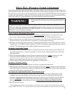
Defrost System: Description and Troubleshooting
Overview
Heat wave and AeroTemp Icebreaker models incorporate an active, time and temperature, hot-gas defrost
system. Basically stated, when an evaporator coil thermostat senses a significant icing condition, the control
circuit reverses the flow of refrigerant, sending hot refrigerant vapor to the outdoor coil. The effect is a rapid
melting of ice and frost, and a quick return to the normal heating mode.