


Page 2
SECTION 2 - INSTALLATION
For commercial or complete installation instructions please, visit www.AquaCal.com for equipment manual.
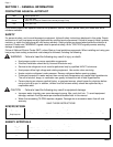
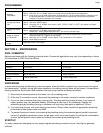
EQUIPMENT CLEARANCES
Keep the area immediately adjacent to the heat pump clear of items such as shrubs and bushes, lawn furniture,
chemicals containers, etc. These items can prevent air from circulating properly through the heater, and will result in
inefficient operation and/or damage to the heat pump.
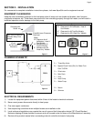
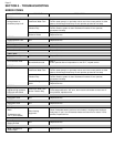
Figure 1 Figure 2
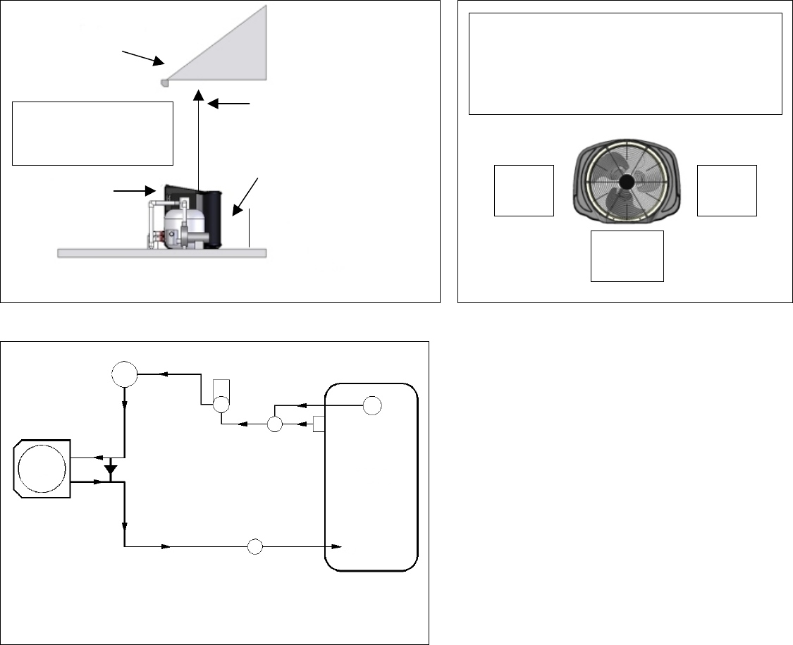
PLUMBING SCHEMATIC
3 = Three Way Valve
B = Bypass Check Valve (5lb) for Water Flow
Over 70 GPM
C = Chlorinator
D = Main Drain
F = Filter
H = Heat Pump
P = Water Pump
Figure 3
R = Return
S = Skimmer
ELECTRICAL REQUIREMENTS
1) Locate the equipment power disconnect within 6-feet of the heater’s electrical enclosure.
2) Never mount power disconnects directly to heat pump.
3) Only use copper conductors.
4) Use sequencing controllers when multiple heaters are installed on site.
5) Local codes and regulations may require the use of a ground fault interruption device (GFI Circuit Breaker).
Nuisance tripping of these devices is common and not covered under the terms of the Manufacturer’s warranty.
6) Review online product manual when connecting external controller devices to heat pump.
Overhang with
Gutter
5 feet Minimum Clearance
Overhead
Rain Run-Off Must Be
Directed Away From
Heater
(Front)
30” Minimum
Clearance
(Rear)
12” Clearance for all
IceBreaker / Heat &
Cool Models
12” Clearance for All
Tropical Models
6” Clearance for SQ
“Heat Only” Models
(Rear)
12” Clearance for All IceBreaker / Heat &
Cool Models
12” Clearance for All TropiCal Models
6” Clearance for SQ “Heat Only” Models
(Side)
12”
(Side)
12”
(Front)
30”
F
P
3 S
D
POOL
R
C
B
H