


2.) Open air control valves to release any possible air
lock.
3.) Make sure all suction and discharge lines are clear
and unobstructed and all valves are opened.
4.) Check for air leaks in the suction line.
LOW WATER FLOW:
1.) Check filter pressure gauge; filter may need
cleaning.
2.) Check for clogged plumbing lines.
3.) Check for worn or damaged impeller.
4.) Check for low voltage.
WATER LEAKS
1.) Check contamination or damage to shaft rotary
seal. Replace if necessary.
2.) Check compression fitting (union connectors);
make sure they are properly aligned and secured.
Hand tighten only. Do not use tools.
3.) Make sure O-ring is properly seated and not
damaged.
NOISES:
1.) Check plumbing vibration-make sure lines are
adequately supported.
2.) Check for cavitation, due to obstruction in or
undersized suction line.
INSTALLATION & OPERATING INSTRUCTIONS
Joint Stick or any other sealants formulated specifically
for plastics.
STARTING & PRIMING PUMP
Do not run unit dry. Always be certain that the pump
casing and/or trap is filled with water before starting the
unit. Allow a reasonable amount of time for priming. If
pump will not start, or will not prime, see trouble
shooting below.
MAINTENANCE
The trap basket should be inspected frequently and kept
clean. To avoid damage to the basket, do not strike
when cleaning. Inspect trap cover O-ring regularly and
replace as necessary.
Keep motor clean. Insure that louvered openings are
free from debris and obstructions. Over a period of time,
the shaft seals may become damaged or worn and must
be replaced.
WINTERIZATION
To prevent damage during freezing conditions, turn off
all electrical power. Drain thoroughly and clean out any
debris. Protect pump and motor from elements by
covering or, if possible, store in a dry, well ventilated
room.
TROUBLE SHOOTING
GENERAL
Your AQUA-FLO pump has been quality built and
engineered to give maximum efficiency under normal
water pumping conditions. Consult the manufacturer for
any other applications.
LOCATION OF PUMP
For best pump performance, locate the system as close
to the water source as possible. Provide adequate
access around the pump for inspection and mainte-
nance.
MODELS LESS TRAP
This model was designed for below water level (flooded
suction) applications. Make sure the pump is installed
at a level that will allow the pump casing (volute) to
completely fill with water.
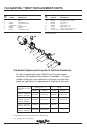
Two quick disconnect compression fittings are included
with your pump for ease of installation and mainte-
nance. Make sure the fittings are correctly aligned with
pump connections to allow the O-ring to make the
proper seal. Hand tighten only. Do not use a wrench
to tighten fittings.
MODELS WITH TRAP
Avoid excessive tightening of pipe or fittings in threaded
suction port in trap. For threaded connection, use
Quick-Seal Teflon Thread Sealing Compound, Plasto-
MOTOR WILL NOT START:
1.) Check Circuit Breakers
2.) Check for incorrect or loose wire connections.
3.) Make sure the correct power supply is being used.
4.) Any on/off switch or pneumatic switch should be in
the "on" mode.
MOTOR OVERHEATING AND CYCLING ON AND OFF:
1.) Check for incorrect or loose wire connections.
2.) Check for low voltage supply (frequently caused by
undersized wire).
3.) Make sure the motor gets a fresh air supply and the
vents are kept unclogged.
MOTOR MAKES HUMMING NOISE BUT WILL NOT
START:
1.) Make sure motor shaft turns free.
2.) Check for jammed impeller or an obstruction in
(volute) casing.
3.) Check for low voltage and undersized wire.
PUMP WILL NOT PRIME:
1.) Make sure pump is installed at the proper level and
the plumbing lines have been correctly installed to
allow the water to enter pump freely.
WARNING - All electrical wiring of the motor installation must be done by a qualified electrician in accordance with
applicable electrical codes. Before working on any motor, be certain that the source of electrical power is off at the
main junction box.
BONDING WIRE - Upon installation of the pump, the motor must be bonded with a No. 8 AWG (8.4mm
2
) solid copper
conductor per National Electric Code. The connection should be from the accessible wire connector on the motor
to all metal parts of the swimming pool, spa, or hot tub structure and to all electrical equipment, metal conduit and
metal piping within 5 feet (1.5m) of the inside walls of a swimming pool, spa or hot tub, when the motor is installed
within 5 feet of the inside walls of the swimming pool, spa, or hot tub.
NOTE: For electrical connections, see wiring diagram on motor rating plate.