4 5
WIRING TERMINAL
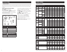
Wire specifications:
18-24 gauge thermostat wire
CAT-5 or equivalent for communication terminals
Installation notes:
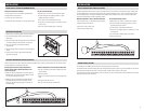
• Ensure power at the HVAC equipment is off.
• Loosen screw terminals, insert stripped wire and
re-tighten.
• Push the excess wire back into the opening and plug
the wall opening to prevent drafts.
Note: If the HVAC system was installed before the
automation system, the HVAC installer may have
powered the thermostat connecting a wire to the
C terminal and installing a jumper wire from the R
terminal to RH or RC. When used with an automation
system, the R and C terminals on the Model 8800
thermostat should only be connected to the same
terminals on the 8819 or a dedicated 24VAC transformer.
There should be no connection to the R or C terminals
coming from the HVAC equipment.
INSTALLATION
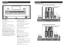
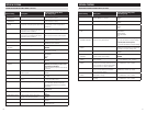
B+ / B- – Receive communication terminal
(reference automation system)
1
A+ / A- – Transmit communication terminal
(reference automation system)
1
C – 24VAC Thermostat power (common) from 8819
R – 24VAC Thermostat power (hot) from 8819
B – Reversing valve for heat
2
O – Reversing valve for cool
2
Y – 1st stage cooling / compressor or dehumidifier
3
Y2 – 2nd stage cooling / compressor
G – Fan
RC – 24VAC supply cooling
4
RH – 24VAC supply heating
4
W2 – 2nd stage heat / auxiliary / E-Heat
W – 1st stage heat / auxiliary / E-Heat / humidifier
3
S1 & S2 – outdoor temperature sensor (optional)
T1 & T2 – remote temperature sensor (optional)
RSA & RSB – 8081 or 8082 Support Module
communication (half duplex)
5
1
Refer to Aprilaire HVAC Automation System Installation Manual
for communication wiring details.
2
O and B terminals are both de-energized when system mode is
OFF or in AUTO when the heating and cooling equipment is idle.
3
When the unit is configured for humidistat mode.
4
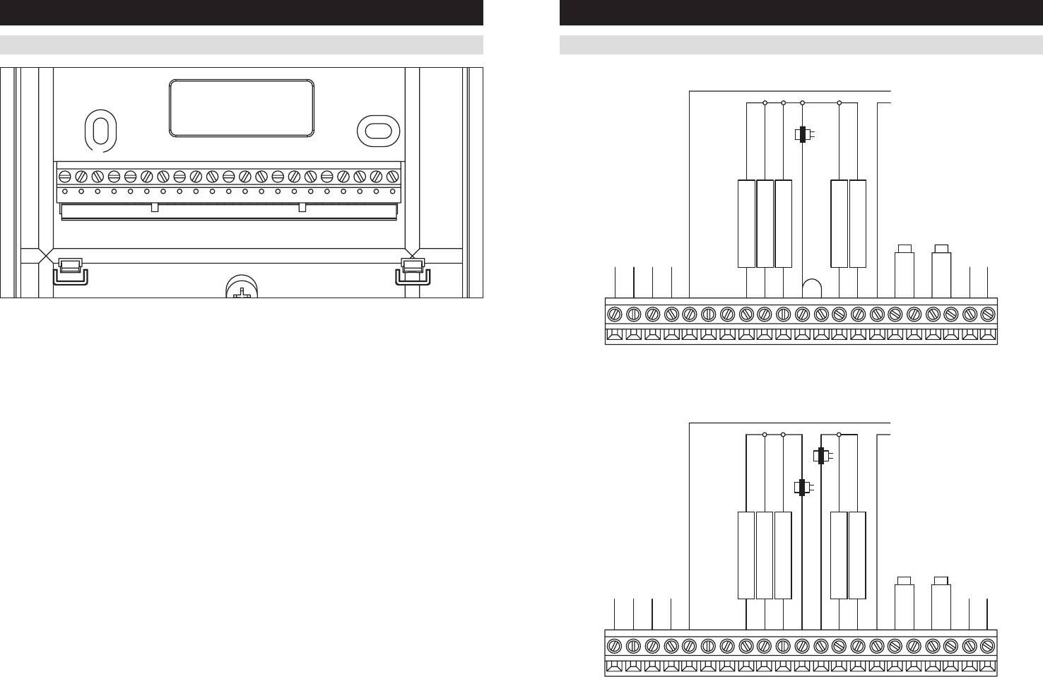
Jumper between RC & RH is used in single transformer systems
(see wiring diagrams).
5
Refer to Support Module literature for wiring details.
C
BY
O
RC RH
G
Y2
W2
RT2
T1
S1
S2
W
B+
A+ A-
B-
RSARSB
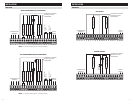
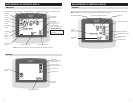
SINGLE TRANSFORMER (USE JUMPER WIRE)
TWO TRANSFORMERS (REMOVE JUMPER WIRE)
JUMPER
OUTDOOR TEMP
SENSOR
1st HEATING
1st COOLING
FAN
2nd HEATING
2nd COOLING
NOT USED
NOT USED
TRANSFORMER
REMOTE TEMP
SENSOR
GY2YO
BW
RC RH W2
S2R
CS
1T1T2A-B-A+B+
RSB RSA
COMMUNICATION
TERMINALS
SUPPORT
MODULE
THERMOSTAT IS POWERED
FROM 8819 OR 24VAC
TRANSFORMER
NOT USED
NOT USED
2nd COOLING
2nd HEATING
FAN
1st COOLING
1st HEATING
OUTDOOR TEMP
SENSOR
COOLING
HEATING
REMOTE TEMP
SENSOR
TRANSFORMER
TRANSFORMER
GY2YO
BW
RC RH W2
S2R
CS
1T1T2A-B-A+B+
RSB RSA
COMMUNICATION
TERMINALS
SUPPORT
MODULE
THERMOSTAT IS POWERED
FROM 8819 OR 24VAC
TRANSFORMER
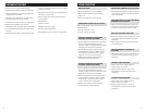
CONVENTIONAL HEAT/COOL
INSTALLATION


