– 22 –
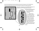
No. 5 – Fan with Heat Call. This switch was set by the installing contractor to operate the thermostat
properly with your equipment. Do not change the position of this switch without consulting with the
installing contractor.
No. 6 – Single-/Multi-Stage Outputs. This switch is factory preset to the ON position, allowing the
thermostat to operate 2-stage heat/cool systems. Do not change the position of this switch without
first consulting your installing contractor. Two-stage systems will not operate properly with the
switch set for single-stage outputs.
No. 7 – Free LED 1 with LCD Filter Symbol. When moved to the ON position, this switch turns on a
Replace Filter icon on the display screen when a 24-volt signal is sent to LED 1 (top left edge of the
thermostat panel, not on the display). If your heating/cooling system has the required controls for
automatically determining when to change the air filter, this feature is beneficial. Consult your
contractor for further information.
No. 8 – Free LED 2 with LCD Wrench Symbol. When moved to the ON position, this switch turns on a
Wrench icon on the display screen when a 24-volt signal is sent to LED 2 (top right edge of the
thermostat panel, not on the display). This feature is beneficial if your heating/cooling system has
the required controls for automatically signaling when a particular problem exists. Consult your
contractor for further information.
110-791B 7/12/01 8:58 AM Page 24


