12
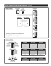
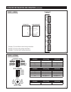
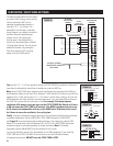
DIP SWITCH DEFINITIONS
MODEL 70 – OFF/ON (SYSTEM SETUP SWITCH #1):
HVAC FAN – OFF/ON (SYSTEM SETUP SWITCH #2):
WHL HOUSE / CONVERTIBLE (SYSTEM SETUP SWITCH #3):
VENT-AUTO / VENT-TIMED (SYSTEM SETUP SWITCH #4):
Determines use of internal RH and temperature sensor or use
of the RH and temperature sensor on the Living Space Control
(Model 70).
MODEL 70-OFF. Uses inlet RH and temperature sensor.
MODEL 70-ON. Uses Living Space Control (Model 70)
RH and Temperature Sensor.
Default is MODEL 70-OFF.
Determines if the HVAC fan activates during a call for
dehumidification.
HVAC FAN-OFF position. The dehumidifier will not activate
the HVAC fan during a call for dehumidification; it will
however activate the HVAC fan for air cycling and ventilation.
HVAC FAN-ON position. The dehumidifier will activate the
HVAC fan during a call for dehumidification as well as for air
cycling and ventilation.
Default is HVAC FAN-OFF.
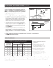
Determines if ventilation is restricted based on outdoor
temperature
VENT-AUTO position. The dehumidifier will measure the
outdoor temperature (through sensor, part # 8052) to
determine if the ventilation damper will open. If the outside
temperature is above 100°F or below 0°F the dehumidifier
will not actuate the ventilation damper terminals (VENT
DAMPER). If the outside temperature is between 0°F - 20°F,
the dehumidifier will only actuate the ventilation damper
terminals (VENT DAMPER) when the HVAC system is making
a call for heat. The dehumidifier will energize the HVAC fan
whether or not the ventilation damper opens.
VENT-TIMED position. The dehumidifier will actuate the
ventilation damper terminals (VENT DAMPER) regardless of
the outdoor temperature.
The default position is VENT-AUTO.
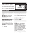
Determines when the dampers are powered open or closed.
CONVERTIBLE position. The damper (DEH) terminals are
actuated when the HVAC equipment is making a call for heat,
cool or fan and the dehumidifier is making an internal blower
call for air sampling or dehumidification.
WHL HOUSE position. The damper (DEH) terminals are
actuated any time the dehumidifier is making an internal
blower call for air sampling or dehumidification.
The default position is WHL HOUSE.
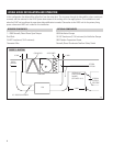
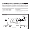
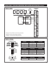
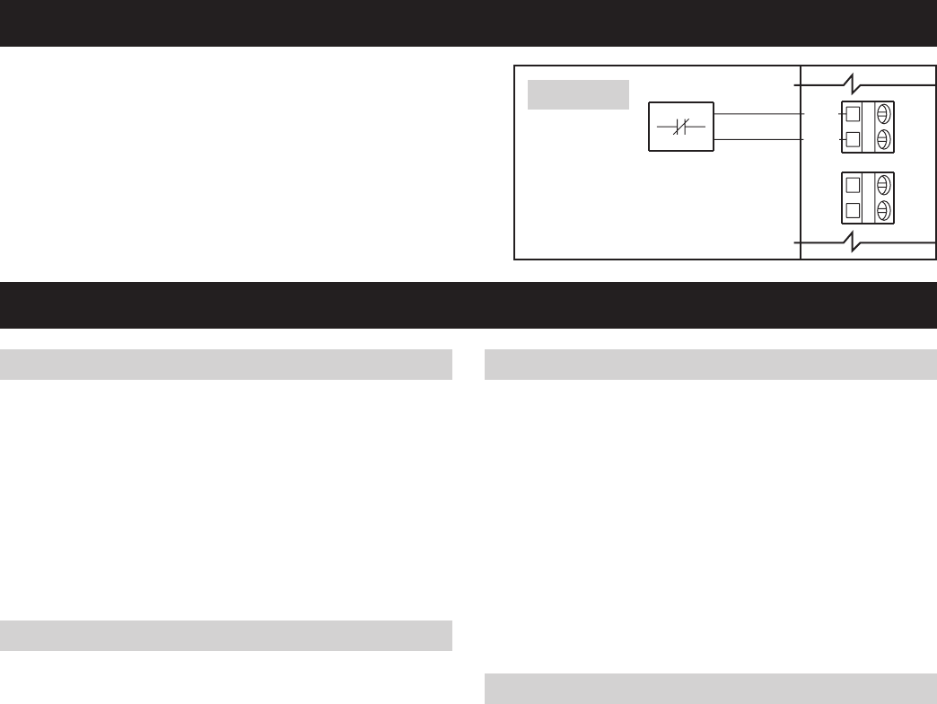
FLOAT SWITCH
If the Model 1700 is installed in an attic, the unit should be
placed in a drain pan with a normally closed condensate overflow
safety switch (also known as a float switch). The float switch
should be wired to the float switch terminals on the dehumidifier
control board. See Figure 18. Remove the jumper at the float
switch terminals. The compressor is disabled when the float
switch is open. The Model 1700 will continue to ventilate when
the float switch is open.
CLOSED FLOAT SWITCH
LOW VOLTAGE NORMALLY
FLOAT
SWITCH SENSOR
ODT
90-968A
FIGURE 18


