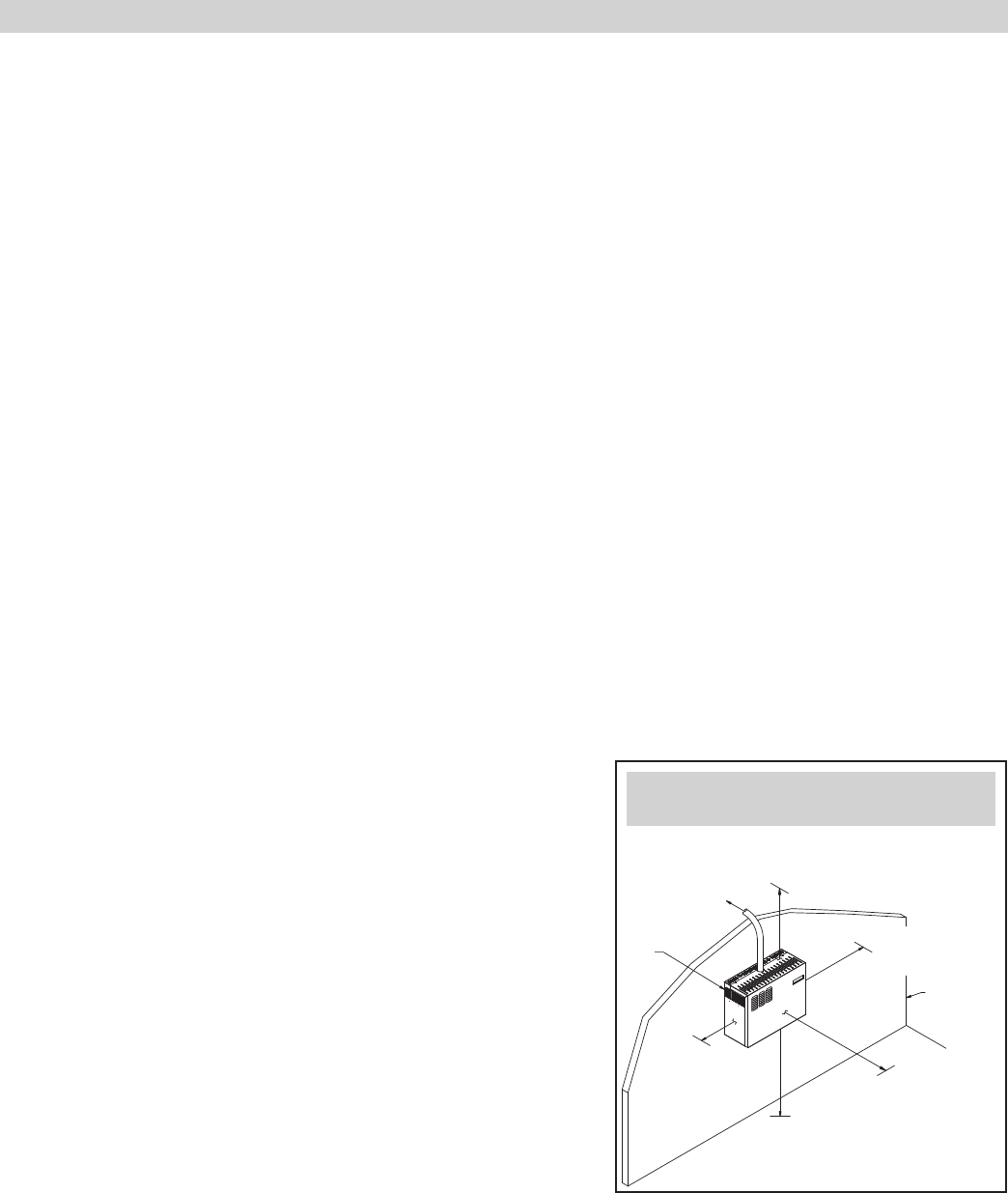
Humidifier Location
When selecting the location of the humidifier, consider the following:
• Proximity to duct
To avoid having to install a drain at the distribution tube in the duct, the distribution tube must be mounted at an elevation
higher than the humidifier. A 10’ (3 m) length of vapor hose is provided with the unit. The hose can be cut if less than 10’ (3 m) is
needed. The hose must have a constant downward slope from the distribution tube to the humidifier of at least 2”/ft (15%). If the
distribution tube must be installed at an elevation lower than the humidifier, install a drip tee and drain as shown in Figure
23.
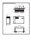
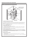
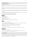
• Required clearances (see Figure 9
)
• Electrical connections
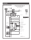
Electrical power supply, water supply piping, and drain piping must also
be considered. Electrical power supply connections are made at the upper
left rear corner of the unit. The control wiring is in the upper right rear
corner. Another consideration when choosing a location for the humidifier
is to avoid areas close to sources of electromagnetic emissions such as
power distribution transformers.
• Plumbing connections
Water supply piping connections are made in the lower right rear corner.
Drain piping connections are made at the lower left rear corner.
CHOOSING A LOCATION FOR HUMIDIFIER COMPONENTS
Before proceeding with the installation, you must first determine where the steam distribution tube will be installed as well as
the humidifier itself.
Steam Distribution Tube and Controls Location
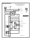
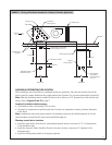
Since this dictates the rest of the installation, first determine where the steam distribution tube will be mounted in the ductwork
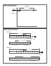
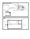
of the HVAC system. Refer to Figure 10 for split system installations and Figure 11 for rooftop unit installations. These figures
also indicate where control devices are to be installed.
Absorption Distance
Absorption distance is the amount of open space in the duct downstream of the distribution tube required for steam to be
absorbed into the air. If the duct contains obstructions such as dampers or elbows within the absorption distance, condensation
on those obstructions can occur. Factors affecting absorption distance include RH of air upstream of the distribution tube, air
temperature inside the duct, air velocity in the duct, and amount of moisture required. In most Model 1150 and 1160 applications,
the clear space required for absorption distance is less than 36”. In fact, in many applications the absorption distance may be
as short as 6”. If the duct has obstructions within 36” of the distribution tube, actual absorption distance can be calculated. In
applications with a large difference between the RH upstream and downstream of the distribution tube, an absorption distance
greater than 36” may be required. To calculate actual absorption distance, follow the procedure listed in the
Appendix.
Right side: 12”
(305 mm)
OM-4011
Top:
18” (460 mm)
Floor: 24” (610 mm)
Supporting
wall
Left side:
12” (305 mm)
Front: 36”
(915 mm)
Secured to
supporting
wall
To distribution tube
FIGURE 9 – Recommended Minimum
Service and Maintenance Clearances
13


