


17
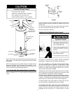
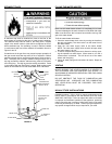
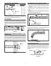
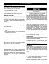
STANDARD VENT ARRANGEMENT
2.6 in.
(67mm)
3.6 in.
(91mm)
2.1 in.
(54.5mm)
WALL
17 in. (432mm) MIN.,*
80 in. (2.03m) MAX.
FIGURE 17
* If the horizontal distance is less than 30 in. (760mm), the
restricter plate must be installed (see Figure 22).
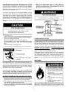
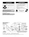
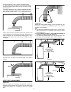
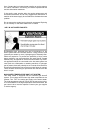
VENT ASSEMBLY
The vent tube and terminal are assembled by the manufacturer
as shown in Figure 18. There are springs fastened inside the
corrugated tube. When the vent tubes are pulled to a required
length, the distances between the springs will still be equally
spaced.
CLAMP
SPRING
FIGURE 18
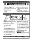
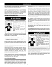
SECURING VENT TERMINATION ASSEMBLY TO THE
EXTERIOR WALL.
Insert the 6 in. (52mm) tube through the clearance hole from
exterior wall then secure the vent terminal to the exterior wall
with 4 screw anchors (not included) appropriate for the type
of wall construction. Caulk the junction of the vent terminal
base plate and the exterior wall with exterior type sealant (not
included).
SEALANT
FIGURE 19
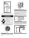
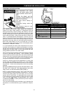
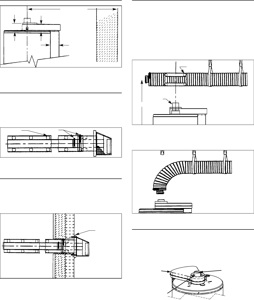
UNCOMPRESSING THE CORRUGATED TUBING
1. Pull the 3-1/8 in. (80mm) corrugated tube towards the water
heater and leave some length over the water heater’s center
for bending.
2. Pull the 6 in. (152mm) corrugated tube toward the water
heater and leave it 1 in. (25mm) shorter than 3-1/8 in. (80mm)
tube.
3. Make sure there are two springs evenly spaced at the bend in
the tube.
4. Use metal hangers to keep venting level or with a slope
upward from the heater to terminal.
REDUCER
SPRING
H
FIGURE 20
Bend the 3-1/8 in. (80mm) and 6 in. (152mm) corrugated tube all
together toward the water heater’s fl ue connection.
FIGURE 21
VENT RESTRICTER PLATE
For short horizontal vent runs (see Figure 17) place the restricter
plate over the fl ue tube reducer before connecting the 3-1/8 in.
(80mm) corrugated tube to the fl ue tube reducer. DO NOT use
the restricter plate if the horizontal run is greater than 30 in.
(760mm).
RESTRICTER
PLATE
FLUE TUBE
REDUCER
UPPER AIR
INLET BOX
FIGURE 22