


16
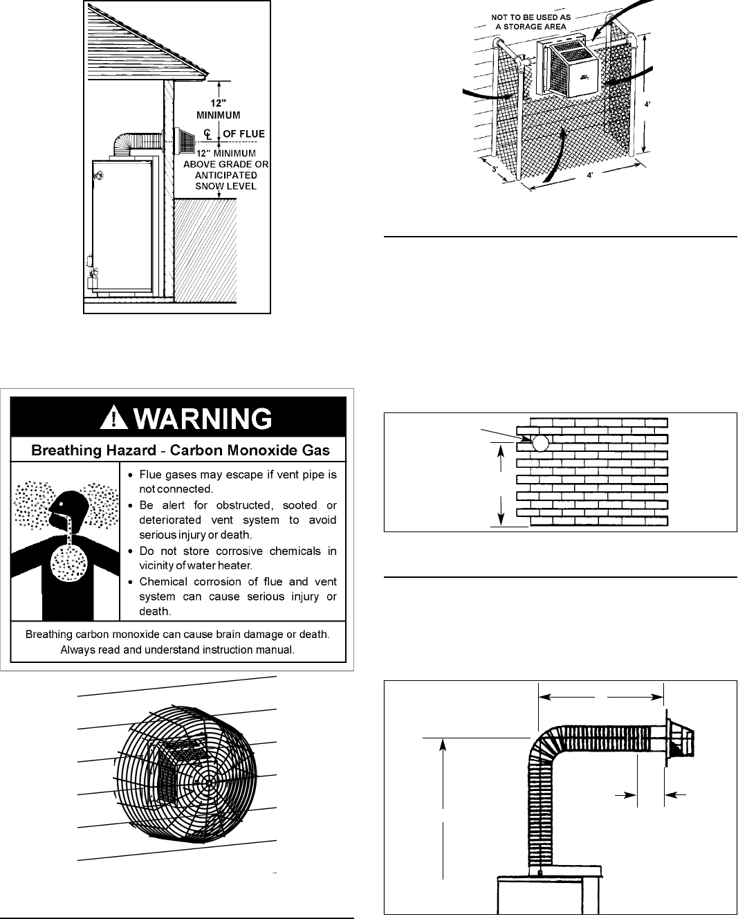
FIGURE 12
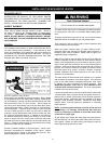
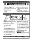
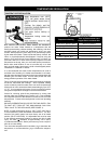
Be sure venting is properly connected to prevent escape of dan-
gerous fl ue gases which could cause deadly asphyxiation.
FIGURE 13
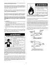
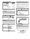
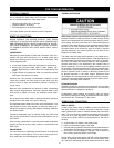
VENT CONNECTIONS
After the location for the vent terminal has been selected as
outlined in Figures 3, 4 & 11, use the following illustrations for
installation:
FIGURE 14
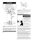
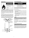
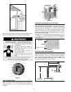
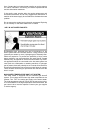
LOCATING CLEARANCE HOLE FOR VENT
Cut a clearance hole, approximately 7 in. (178mm) in diameter,
through the exterior wall for the vent assembly. The minimum
height should not be less than 68 in. (1.72m) for 40 gal. models
and not less than 76 in. (1.93m) for 50 gal. and 50 gal. Hi-Input
models, as measured from the hole center to bottom of water
heater. The maximum height recommended is 80 in. (2.03m) or
in compliance with Figure 16.
Where the wall is combustible and the wall thickness is over 14
in. (356mm), 1 in. (25mm) clearance to combustible materials
around the vent terminal is needed. The fi rst 14 in. (356mm) is
zero clearance.
7 in. (178mm )
DIAMETER
BOTTOM OF HEATER
MINIMUM
(SEE TEXT)
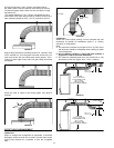
FIGURE 15
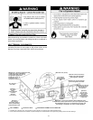
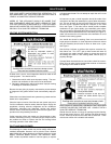
HIGH RISE VENT ARRANGEMENT
When the height H (From vent terminal center line to bottom of
heater) is over 80 in. (2.03m), it is a high rise vent arrangement.
In this case the minimum distance “D” from the center of the
water heater to the outside wall surface is 22 in. (560mm), and
the maximum height of “H” is 12 ft. (3.66m).
TO BOTTOM
OF HEATER
WALL THICKNESS
10 in.
(254mm)
(REF)
D
H
FIGURE 16