


2
These designs comply with the latest version of the American National
Standard for Gas Water Heaters, Volume III, ANSI Z21.10.3 / CSA 4.3 M 98
as an automatic circulating tank water heater, and automatic storage water
heaters.
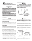
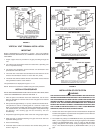
Detailed installation diagrams are found in this manual. These diagrams will
serve to provide the installer with a reference for the materials and methods
of piping necessary. It is highly essential that all water, gas piping and
wiring be installed as shown on the diagrams.
Particular attention should be given to the installation of thermometers at
the locations indicated on the diagrams as these are necessary for checking
the proper functioning of the heater.
In addition to these instructions, the equipment shall be installed in
accordance with those installation regulations in force in the local area
where the installation is to be made. These shall be carefully followed in all
cases. Authorities having jurisdiction should be consulted before
installations are made.
In the absence of local codes, the installation must comply with the latest
editions of the National Fuel Gas Code, ANSI Z223.1/NFPA 54 and the
National Electric Code, NFPA 70 CAN/CSA 149.1 or .2 and CSA 2C22.1. The
former is available from the CSA International, 8501 East Pleasant Valley
Road, Cleveland, OH 44131, and both documents are available from the
National Fire Protection Association, 1 Batterymarch Park, Quincy, MA 02269.
FOREWORD
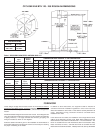
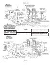
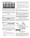
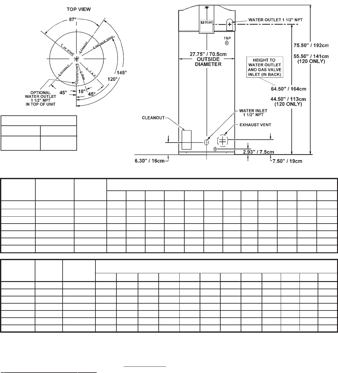
CYCLONE XHE BTH 120 - 250 ROUGH-IN-DIMENSIONS
TEMPERATURE RISE - DEGREES °C - LITERS PER HOUR
Approx.
Input Liter
Model kW Capacity 17°C 22°C 28°C 33°C 39°C 44°C 50°C 56°C 61°C 67°C 72°C 78°C
BTH - 120 37 Nat. 227 1798 1348 1079 898 768 674 598 538 488 450 416 386
BTH - 120 35 L.P. 227 1726 1295 1037 863 738 647 575 519 469 432 397 371
BTH - 150 44 Nat. 379 2158 1616 1295 1079 924 810 719 647 587 538 500 462
BTH - 150 44 L.P. 379 2158 1616 1295 1079 924 810 719 647 587 538 500 462
BTH - 199 58 Nat. 379 2873 2154 1726 1438 1230 1079 958 863 784 719 662 617
BTH - 199 54 L.P. 379 2661 1995 1597 1329 1139 996 886 799 727 666 613 572
BTH - 250 70 Nat. 379 3452 2589 2071 1726 1480 1295 1151 1037 939 863 795 738
Recovery capacities are based on heater performance at 94% thermal efficiency.
Table 1. RECOVERY CAPACITIES - NATURAL GAS / L.P.
TEMPERATURE RISE - DEGREES °F - GALLONS PER HOUR
Approx.
Input Gallon
Model BTU/Hr. Capacity 30 40 50 60 70 80 90 100 110 120 130 140
BTH - 120 125,000 Nat. 60 475 356 285 237 203 178 158 142 129 119 110 102
BTH - 120 120,000 L.P. 60 456 342 274 228 195 171 152 137 124 114 105 98
BTH - 150 150,000 Nat. 100 570 427 342 285 244 214 190 171 155 142 132 122
BTH - 150 150,000 L.P. 100 570 427 342 285 244 214 190 171 155 142 132 122
BTH - 199 199,900 Nat. 100 759 569 456 380 325 285 253 228 207 190 175 163
BTH - 199 185,000 L.P. 100 703 527 422 351 301 263 234 211 192 176 162 151
BTH - 250 240,000 Nat. 100 912 684 547 456 391 342 304 274 248 228 210 195
GAS VALVE PIPING
BTH-120 1/2" NPT
BTH-150,
199 & 250 3/4" NPT