


12
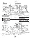
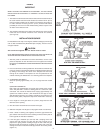
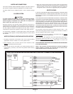
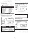
BLOCKED OUTLET PROVER SWITCH
(SEE FIGURE 13)
The Blocked Outlet Prover Switch is set up to shut the unit off when a build-
up of positive pressure in the exhaust vent pipe occurs. This switch is a
positive pressure switch that requires an increase in pressure to change
the electrical contacts from normally closed to open. When this switch
prevents the unit from igniting, most likely the exhaust is blocked by some
means Check to see if the condensate is allowed to flow freely from the
exhaust elbow and for obstructions in the exhaust venting and exhaust
vent terminal. Also verify that there is no more than fifty equivalent feet
(15.2 m) of three inch PVC vent pipe on the exhaust.
BLOCKED INLET PROVER SWITCH
(SEE FIGURE 13)
The Blocked Inlet Prover Switch is set up to shut the unit off when a build-
up of negative pressure in the intake vent pipe occurs. This switch is a
negative pressure switch that requires an increase in negative pressure
to change the electrical contacts from normally closed to open. The switch
is connected to the pressure tap on the PVC flange connected to the inlet
of the blower. When this switch prevents the unit from igniting, most likely
the intake is blocked by some means. Check to see if there is no more than
fifty equivalent feet (15.2 m) of three inch PVC vent pipe on the intake. Also
verify that the intake and intake vent terminal is free of obstructions that
may prevent air from entering the unit.
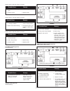
LOW GAS PRESSURE SWITCH
(SEE FIGURE 13)
The Low Gas Switch (LGS) is a single-pole, normally open pressure switch
that will close its contacts when a rising pressure of 5.0 in. (1.25Kpa) W.C.
is encountered. The contacts will open when the pressure falls below the
fixed set point of 5.0 in. (1.25Kpa) W.C. The LGS monitors the gas supply
pressure to the heater. If the gas supply falls below 5.0 in. (1.25Kpa) W.C.,
the main burner is extinguished (if heater is running) or the heater will not
start up.
ON/OFF SWITCH
The ON/OFF Switch is a single-pole, single-throw rocker switch. This
switch provides 120V from the line source to the heater.
CAUTION
THE WATER HEATER IS POLARITY SENSITIVE. BEFORE APPLYING
ELECTRICITY TO THIS HEATER BE CERTAIN THAT SUPPLY NEUTRAL
WIRE TO GROUND CHECK INDICATES ZERO VOLTAGE.
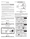
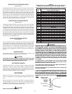
HOT SURFACE IGNITER
The Hot Surface Igniter is a device that ignites the main burner by high
temperature (>1800°F or >982°C). When 120VAC is applied to the igniter,
sufficient heat is generated to ignite the main burner. Although improvements
have been made to strengthen the igniter, it is still fragile and care must be
taken when handling the igniter to prevent breakage.
GAS PIPING
Contact your local gas service company to ensure that adequate gas
service is available and to review applicable installation codes for your
area.
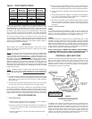
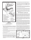
Size the main gas line in accordance with Table 3. The figures shown are
for straight lengths of pipe at 0.5 in. (125Pa) W.C. pressure drop, which is
considered normal for low pressure systems Note that fittings such as
elbows and tees will add to the pipe pressure drop.
CAUTION
DO NOT USE FLEXIBLE GAS PIPING.
TABLE 3
MAXIMUM CAPACITY OF PIPE IN CUBIC FEET OF GAS PER HOUR
(Based upon a Pressure Drop of 0.5 inch Water Column
and 0.6 Specific Gravity Gas and max. gas pressure of 0.5 psig)
WARNING
THE HEATER IS NOT INTENDED FOR OPERATION AT HIGHER THAN 14.0"
WATER COLUMN (1/2 POUND or 3.45Kpa PER SQUARE INCH) SUPPLY
GAS PRESSURE. HIGHER GAS SUPPLY PRESSURES REQUIRE
SUPPLEMENTAL REDUCING SERVICE REGULATION. EXPOSURE TO
HIGHER GAS SUPPLY PRESSURE MAY CAUSE DAMAGE TO THE GAS
CONTROLS WHICH COULD RESULT IN FIRE OR EXPLOSION. IF
OVERPRESSURE HAS OCCURRED SUCH AS THROUGH IMPROPER
TESTING OF GAS LINES OR EMERGENCY MALFUNCTION OF THE
SUPPLY SYSTEM THE GAS VALVE MUST BE CHECKED FOR SAFE
OPERATION. MAKE SURE THAT THE OUTSIDE VENTS ON THE SUPPLY
REGULATORS AND THE SAFETY VENT VALVES ARE PROTECTED
AGAINST BLOCKAGE. THESE ARE PARTS OF THE GAS SUPPLY
SYSTEM, NOT THE HEATER. VENT BLOCKAGE MAY OCCUR DURING
ICE STORMS.
IT IS IMPORTANT TO GUARD AGAINST GAS VALVE FOULING FROM
CONTAMINANTS IN THE GAS WAYS. SUCH FOULING MAY CAUSE
IMPROPER OPERATION, FIRE OR EXPLOSION.
IF COPPER SUPPLY LINES ARE USED THEY MUST BE INTERNALLY
TINNED AND CERTIFIED FOR GAS SERVICE.
BEFORE ATTACHING THE GAS LINE BE SURE THAT ALL GAS PIPE IS
CLEAN ON THE INSIDE.
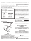
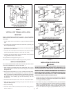
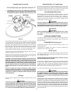
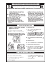
TO TRAP ANY DIRT OR FOREIGN MATERIAL IN THE GAS SUPPLY LINE,
A DIRT LEG (SOMETIMES CALLED A SEDIMENT TRAP OR DRIP LEG)
MUST BE INCORPORATED IN THE PIPING (SEE FIG. 14). THE DIRT LEG
MUST BE READILY ACCESSIBLE AND NOT SUBJECT TO FREEZING
CONDITIONS. INSTALL IN ACCORDANCE WITH RECOMMENDATIONS
OF SERVING GAS SUPPLIERS. REFER TO THE NATIONAL FUEL GAS
CODE.
FIGURE 14
LENGTH NORMAL IRON PIPE SIZES (INCHES)
IN INPUT IN THOUSANDS BTU/HR
FEET 1/2" 3/4" 1" 1 1/4" 1 1/2" 2" 2 1/2" 3" 4"
10 175 360 680 1400 2100 3960 6300 11000 23000
20 120 250 485 950 1460 2750 4360 7700 15800
30 97 200 375 770 1180 2200 3520 6250 12800
40 82 170 320 660 990 1900 3000 5300 10900
50 73 151 285 580 900 1680 2650 4750 9700
60 66 138 260 530 810 1520 2400 4300 8800
70 61 125 240 490 750 1400 2250 3900 8100
80 57 118 220 460 690 1300 2050 3700 7500
90 53 110 205 430 650 1220 1950 3450 7200
100 50 103 195 400 620 1150 1850 3250 6700
125 44 93 175 360 550 1020 1650 2950 6000
150 40 84 160 325 500 950 1500 2650 5500
175 37 77 145 300 460 850 1370 2450 5000
200 35 72 135 280 430 800 1280 2280 4600
LENGTH NORMAL IRON PIPE SIZES (INCHES)
IN INPUT IN KW
METERS 1/2" 3/4" 1" 1 1/4" 1 1/2" 2" 2 1/2" 3" 4"
3.0 51 105 199 410 615 1160 1845 3221 6735
6.1 35 73 142 278 428 805 1277 2255 4626
9.1 28 59 110 225 346 644 1031 1830 3748
12.2 24 50 94 193 290 556 878 1552 3192
15.2 21 44 83 170 264 492 776 1391 2840
18.3 19 40 76 155 237 445 703 1259 2577
21.3 18 37 70 143 220 410 659 1142 2372
24.4 17 35 64 135 202 381 600 1083 2196
27.4 16 32 60 126 190 357 571 1010 2108
30.5 15 30 57 117 182 337 542 952 1962
38.1 13 27 51 105 161 299 483 864 1757
45.7 12 25 47 95 146 278 439 776 1610
53.3 11 23 42 88 135 249 401 717 1464
61.0 10 21 40 82 126 234 375 688 1347