1212
1212
12
7. Set primary system temperature control dial (thermostat) to
desired setting.
WARNING
DO NOT INCREASE GAS PRESSURE ABOVE THAT SPECIFIED
ON THE RATING PLATE, AS OVERFIRING WILL RESULT IN
DAMAGE TO THE BOILER, AS WELL AS INCREASED RISK OF
FIRE, SOOTING AND ASPHYXIATION.
If gas pressure regulator cannot be adjusted to correct pressure
with sufficient gas pressure at the valve, replace with new gas
valve.
VENTING THE BOILER - STANDARD VENTING
WARNING
THE INSTRUCTIONS IN THIS SECTION ON VENTING THE
BOILER MUST BE FOLLOWED TO AVOID CHOKED COMBUSTION
OR RECIRCULATION OF FLUE GASES. SUCH CONDITIONS
CAUSE SOOTING OR RISKS OF FIRE AND ASPHYXIATION.
TYPE B VENTING MAY BE USED WITH THESE BOILERS. ALL
LOCAL UTILITY REGULATIONS ON VENTING SHOULD BE
FOLLOWED.
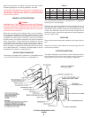
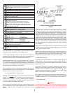
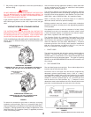
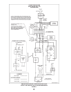
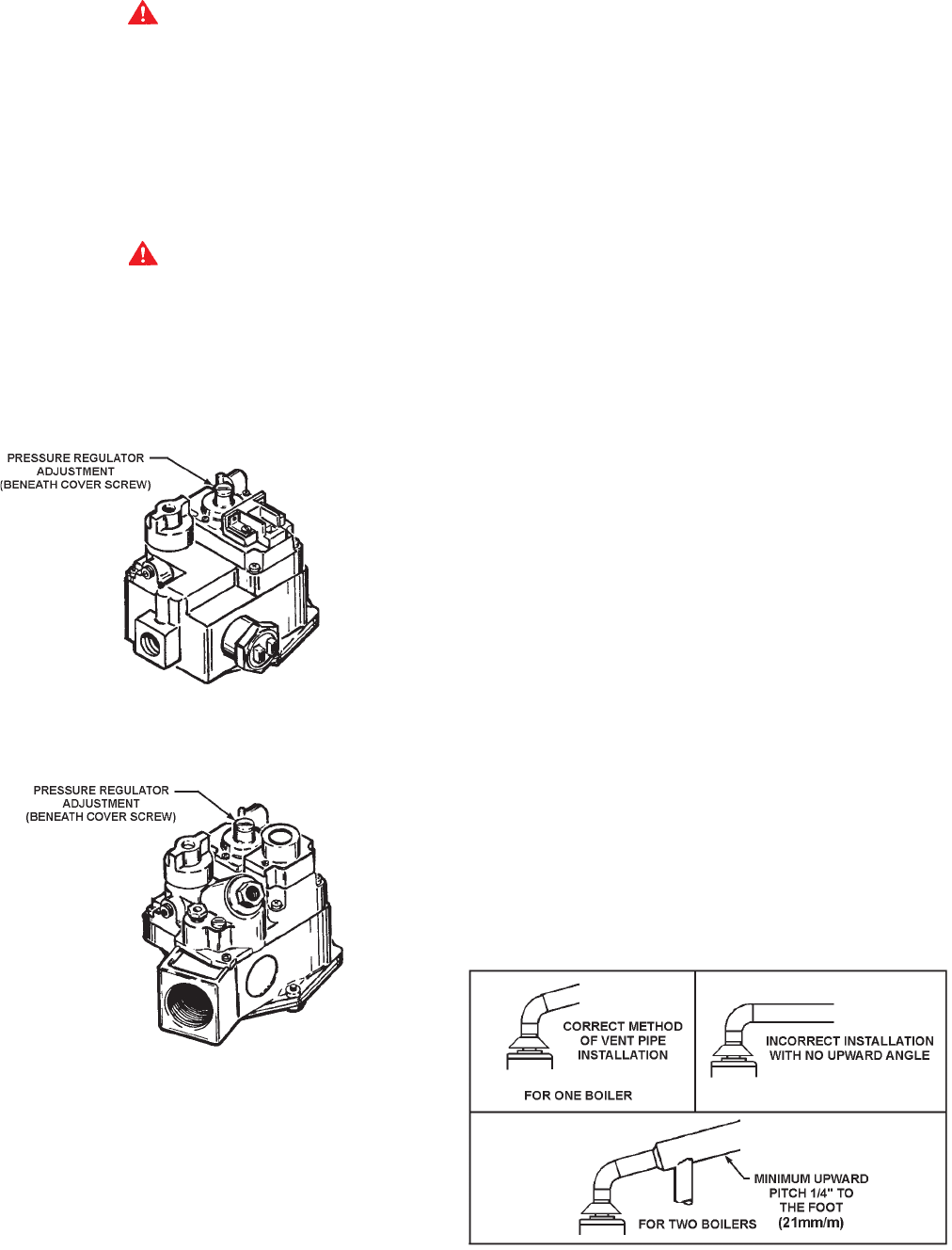
ROBERTSHAW
®
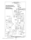
7000 DERHC
HWB/HW-300, 399,-420, -520, -610, -670 NATURAL GAS WITH I.I.D.
HW-300, -399, -420, -520, -670 LP GAS WITH I.I.D. U.S. ONLY
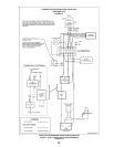
ROBERTSHAW
®
7000 ERHC (LP)
HWB/HW-300, 399,-420, -520, -610 SINGLE STAGE
STANDING PILOT, CANADIAN ONLY
FIGURE 6
For boilers for connection to gas vents or chimneys, vent sizing,
installation and termination shall be in accordance with Part 7,
Venting of Equipment, of the National Fuel Gas Code, ANSI Z223.1,
or Section 7, Venting Systems and Air Supply for Appliances, of the
CAN/CSA B149.1-00, Installation Codes, or applicable provisions
of the local building codes.
Vent connectors serving appliances vented by natural draft shall
not be connected into any portion of mechanical draft systems
operating under positive pressure.
The minimum distance from adjacent public walkways, adjacent
buildings, openable windows and building openings shall not be
less than those values specified in the National Fuel Gas Code,
ANSI Z223.1 and/or CAN/CSA B149.1-00, Installation Codes;
Stack or chimney must be a minimum height of 12" (305mm)
above the annual snow fall to prevent blockage.
Building materials must not come in contact with combustion
products from stack or chimney, due to the degradating properties
of flue products.
Flue products must have a minimum clearance of 4 feet (1.22m)
horizontally from, and in no case above or below, unless a 4-foot
(1.22m) horizontal distance is maintained, from electric meters,
gas meters, regulators and relief equipment.
The Canadian B149.1-00, Installation Code specifies a 6 foot
horizontal vent terminal clearance to gas and electric meters and
relief devices (this clearance is specified as 4 feet in the U.S.
under the National Fuel Gas Code, ANSI/Z223.1). Therefore
instruction provision 134.1-b19(d), which specifies compliance
with the 4 foot clearance, as applies in the U.S. only, and the
B149.1-00 Installation Code applies in Canada.
1. DRAFT HOOD
The draft hood furnished with this boiler must be installed without
alteration. Provision must be made if the boiler is installed in
confined space or a small boiler room to accommodate draft hood
spillage and avoid risks described above. The upper air opening
called for in the AIR REQUIREMENTS section of this manual is for
this purpose.
2. VENT CONNECTION
Size and install proper size vent pipe. Do not reduce pipe size to
less than that of the draft hood outlet.
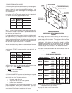
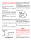
Horizontal runs of vent pipe shall be securely supported by
adequately placed (approximately every 4 feet or 1 meter),
noncombustible hangers and/or slip joints suitable for the weight
and design of the materials employed to prevent sagging and to
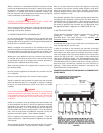
maintain a minimum upward slope of 1/4" (21mm/m) per foot
from the boiler to the vent terminals, fig. 7. Dampers or other
obstructions must not be installed in the vent. Be sure that the vent
pipe does not extend beyond the inside wall of the chimney.
VENT PIPE INSTALLATION
FIGURE 7
® Robertshaw is a registered trademark of Fulton Controls Corp.


