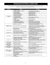
27
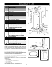
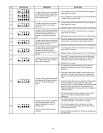
Key No. Part Description
1 Burner Assembly
2 Burner Head
3 Burner Orifi ce
4 Burner Tube
5 HSI Ignition Assembly
6 Inner Door
7 Inner Door Gasket
8 Flue Baffl e
9 Flue Restrictor
10 Blower Assembly
11 Air Intake Screen - Base Pan
12 Inlet Tube
13 Gas Control Valve
14 Drain Valve
15 Drain Valve Washer
16 Outer Door (may appear different than shown)
17 Anode Rod
18 Temperature-Pressure Relief Valve
19 Viewport Bracket
20 Viewport Glass
21 Viewport Insulation
22 20” Dia. Drain Pan w/Side Drain (optional)
22” Dia. Drain Pan w/Side Drain (optional)
24” Dia. Drain Pan w/Side Drain (optional)
26” Dia. Drain Pan w/Side Drain (optional)
*23 Instruction Manual
24 Air Intake Screen - Blower Assembly
25 FV Sensor
26A FV Sensor Bracket (40K & 50K models only)
26B FV Sensor Bracket (55K & 62.5K models only)
**27 Nipple with Heat Trap
**28 Secondary Anode with Heat Trap
* Not Shown.
** Optional
Now that you have purchased this water heater, should a need ever exist
for repair parts or service, simply contact the company it was purchased
from or direct from the manufacturer listed on the rating plate on the
water heater.
Be sure to provide all pertinent facts when you call or visit.
Selling prices will be furnished on request or parts will be shipped
at prevailing prices and you will be billed accordingly.
The model number of your Gas Water Heater will be found on the rating
place located above the gas control valve.
WHEN ORDERING REPAIR PARTS, ALWAYS GIVE THE FOLLOWING
INFORMATION:
• MODEL NUMBER
• TYPE GAS (NATURAL OR PROPANE (L.P.)
• SERIAL NUMBER
• PART DESCRIPTION
THIS IS A REPAIR PARTS LIST, NOT A PACKING LIST.
REPAIR PARTS LIST
22
DRAIN PAN
1
BURNER ASSEMBLY
OUTER DOOR
(ALTERNATE)
16


