


11
GROUNDED IN ACCORDANCE WITH LOCAL CODES OR IN
THE ABSENCE OF LOCAL CODES, WITH THE NATIONAL
ELECTRICAL CODE, ANSI/NFPA 70.
If local codes do not permit use of a flexible power supply cord.
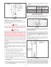
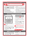
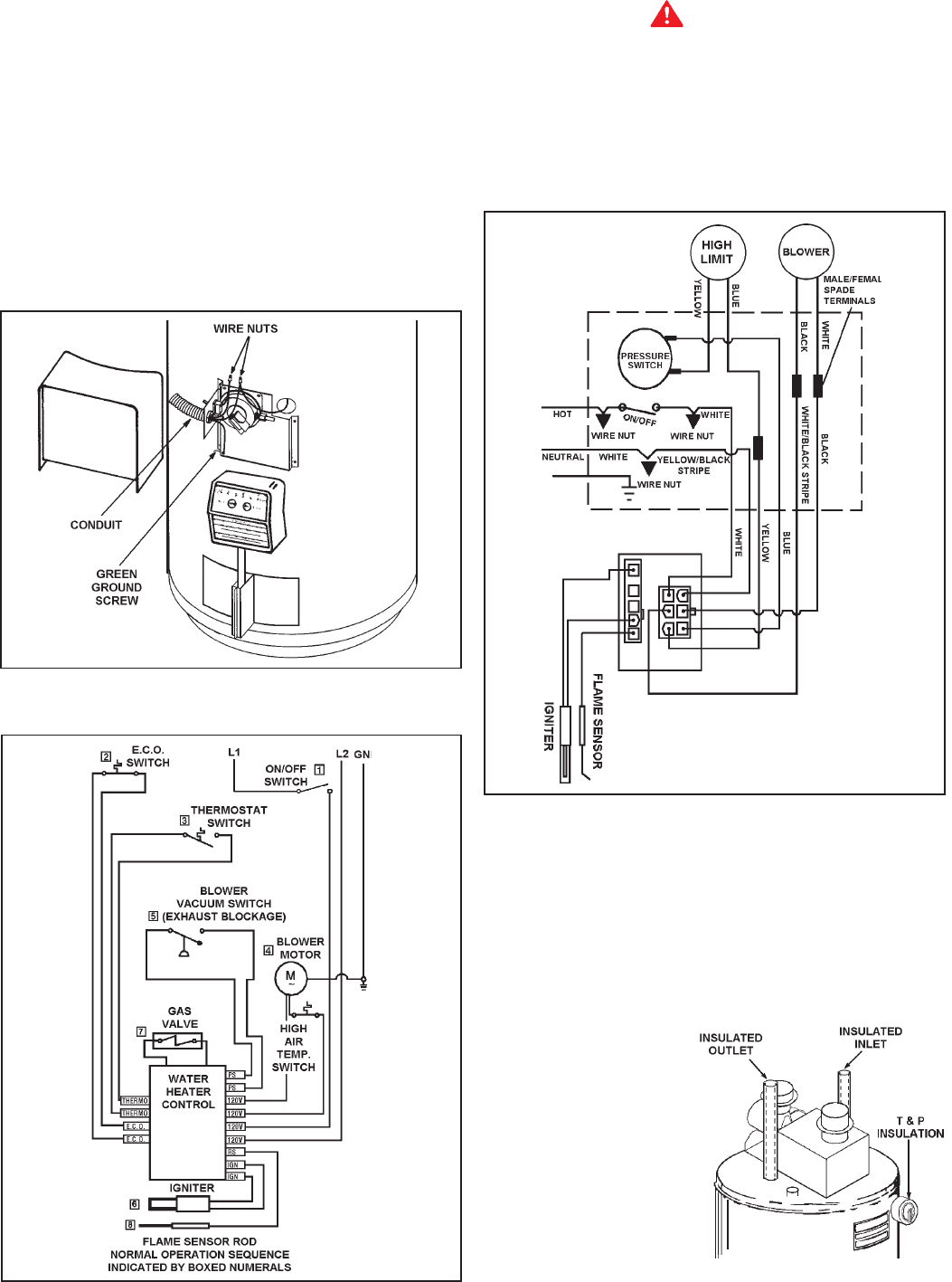
OPTIONAL Field Installed Wiring
1. Remove screws to remove wiring junction cover.
2. A standard 1/2" conduit opening has been made in the water
heater junction box for the conduit connection.
3. Use wire nuts and connect the power supply wiring to the
wires inside the water heater's junction box.
4. Be certain that neutral and line connections are not reversed
when making these connections.
5. Replace front plate and secure with screws.
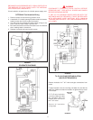
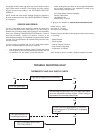
FIGURE 24.
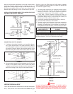
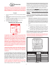
SCHEMATIC DIAGRAMS
FIGURE 25.
WARNING
DISCONNECT FROM ELECTRICAL SUPPLY BEFORE
SERVICING UNIT. REPLACE ALL DOORS AND PANELS
BEFORE OPERATING HEATER.
IF ANY OF THE ORIGINAL WIRES SUPPLIED WITH THE
APPLIANCE MUST BE REPLACED, IT MUST BE REPLACED
WITH APPLIANCE WIRE MATERIAL WITH MINIMUM
TEMPERATURE RATING OF 105°C AND A MINIMUM SIZE OF
NO. 18 AWG.
FIGURE 26.
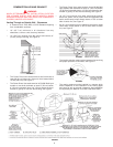
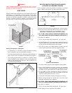
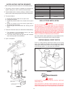
T & P VALVE AND PIPE INSULATION
(ON SELECTED MODELS)
Remove insulation for T & P valve and pipe connections from
carton.
Fit pipe insulation over the incoming cold water line and the hot
water line. Make sure that the insulation is against the top cover
of the heater.
Fit T & P valve insulation
over valve. Make sure that
the insulation does not
interfere with the level of
the T & P valve.
Secure all insulation
using tape.
FIGURE 27.