


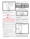

5
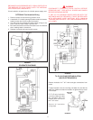
CLOSED WATER SYSTEM
A closed system will exist if a back-flow preventer (check valve),
pressure reducing valve, or other similar device is installed in
the cold water line between the water heater and the street main
(or well). Excessive pressure may develop due to the thermal
expansion of heated water causing premature tank failure or
intermittent relief valve operation. This type of failure is not covered
by the limited warranty. An expansion tank may be necessary in
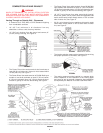
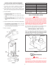
the cold water supply to alleviate this situation, see Figure 1.
Contact the local plumbing authority.
If the temperature and pressure relief valve on the appliance
discharges periodically, this may be due to thermal expansion
in a closed water supply system. Contact the water supplier or
local plumbing inspector on how to correct the situation.
Do not
plug the temperature and pressure relief valve.
GAS CONNECTIONS
The minimum gas supply pressure for input adjustment is
5.0" W.C. (1.25 kPa) for natural gas 11.0" W.C. (2.74 kPa) for propane.
THE HEATER IS NOT INTENDED FOR OPERATION AT HIGHER
THAN 10.5" (2.6 kPa) FOR NATURAL & 13.0" (3.24 kPa) FOR
PROPANE WATER COLUMN SUPPLY PRESSURE. EXPOSURE
TO HIGHER GAS SUPPLY PRESSURE MAY CAUSE DAMAGE TO
THE CONTROL WHICH COULD RESULT IN FIRE OR EXPLOSION.
If overpressure has occurred such as through improper testing of gas
lines or emergency malfunction of the supply system, the control must
be checked for safe operation. Make sure that the outside vents on the
supply regulators and the safety vent valves are protected against
blockage. These are parts of the gas supply system not the
heater. Vent blockage may occur during ice storms.
IT IS IMPORTANT TO GUARD AGAINST CONTROL FOULING
FROM CONTAMINANTS IN THE GAS WAYS. SUCH FOULING
MAY CAUSE IMPROPER OPERATION, FIRE OR EXPLOSION.
All piping must comply with local codes and ordinances or with
the National Fuel Gas Code (ANSI Z223.1, NFPA 54) whichever
applies. Copper and brass tubing and fittings (except tin lined
copper tubing) shall not be used.
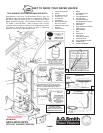
REFER TO FIGURE 1 FOR CONNECTION DETAILS. BEFORE
ATTACHING THE GAS LINE BE SURE THAT ALL GAS PIPE IS
CLEAN ON THE INSIDE.
TO TRAP ANY DIRT OR FOREIGN MATERIAL IN THE GAS SUPPLY
LINE, A DIRT LEG (SOMETIMES CALLED DRIP LEG) MUST BE
INCORPORATED IN THE PIPING, SEE FIGURE 1. The dirt leg must
be readily accessible. Install in accordance with recommendations of
serving gas supplier. Refer to the current edition of ANSI Z223.1.
To prevent damage, care must be taken not to apply too much
torque when attaching gas supply pipe to gas valve inlet. The
valve inlet has a hexagon shape for use with a backup wrench.
Apply joint compounds (pipe dope) sparingly and only to the
male threads of pipe joints. Do not apply compound to the first
two threads. Use compounds resistant to the action of liquefied
petroleum gases. Do not use teflon tape on gas valve.
DISCONNECT THE APPLIANCE AND ITS INDIVIDUAL SHUT OFF
VALVE FROM THE GAS SUPPLY PIPING SYSTEM DURING ANY
SUPPLY PRESSURE TESTING EXCEEDING 1/2 PSI
(3.5 kPa). GAS SUPPLY LINE MUST BE CAPPED WHEN
DISCONNECTED FROM THE HEATER. FOR TEST PRESSURES AT
1/2 PSI (3.5 kPa) OR LESS, THE APPLIANCE NEED NOT BE
DISCONNECTED, BUT MUST BE ISOLATED FROM THE SUPPLY
PRESSURE TEST BY CLOSING THE MAIN MANUAL GAS VALVE.
BEFORE PLACING THE HEATER IN OPERATION, CHECK
FOR GAS LEAKAGE. USE SOAP AND WATER SOLUTION OR
OTHER MATERIAL ACCEPTABLE FOR THIS PURPOSE. DO NOT
USE MATCHES, CANDLES, FLAME OR OTHER SOURCES OF
IGNITION TO LOCATE GAS LEAKS.
RELIEF VALVE (P)- See FIGURE 1.
A NEW TEMPERATURE AND PRESSURE RELIEF VALVE
COMPLYING WITH THE STANDARD FOR RELIEF VALVES AND
AUTOMATIC GAS SHUT OFF DEVICES FOR HOT WATER
SUPPLY SYSTEMS, ANSI Z21.22 (CURRENT EDITION) MUST
BE INSTALLED IN THE HEATER IN THE MARKED OPENING
PROVIDED. THE VALVE MUST BE OF A SIZE (INPUT RATING)
THAT WILL BE ADEQUATE FOR YOUR SIZE HEATER.
Check the metal tag on the relief valve and compare it to the
heater’s rating plate. The pressure rating of the relief valve must
not exceed the working pressure shown on the rating plate of the
heater. In addition, the hourly Btu rated temperature steam
discharge capacity of the relief valve shall not be less than the
input rating of the heater.
NO VALVE IS TO BE PLACED BETWEEN
THE RELIEF VALVE AND TANK. DO NOT PLUG THE RELIEF VALVE.
The drain line connected to this valve must not contain a reducing
coupling or other restriction and must terminate near a suitable
drain to prevent water damage during valve operation. The
discharge line shall be installed in a manner to allow complete
drainage of both the valve and line.
DO NOT THREAD, PLUG OR
CAP THE END OF THE DRAIN LINE.
VENTING
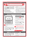
WARNING
NEVER OPERATE THE HEATER UNLESS THE INTAKE AND
EXHAUST ARE VENTED TO THE OUTDOORS AND HAS ADEQUATE
AIR SUPPLY TO AVOID RISKS OF IMPROPER OPERATION, FIRE,
EXPLOSION, OR ASPHYXIATION. IF THE WATER HEATER IS BEING
INSTALLED AS A REPLACEMENT FOR AN EXISTING POWER
VENTED HEATER IN PRE-EXISTING VENTING, A THOROUGH
INSPECTION OF THE EXISTING VENTING SYSTEM MUST BE
PERFORMED PRIOR TO ANY INSTALLATION WORK. VERIFY THAT
THE CORRECT MATERIAL AS DETAILED ABOVE HAS BEEN USED,
AND THAT THE MINIMUM OR MAXIMUM VENT LENGTHS AND
TERMINAL LOCATION AS DETAILED IN THIS MANUAL HAVE BEEN
MET. CAREFULLY INSPECT THE ENTIRE VENTING SYSTEM FOR
ANY SIGNS OF CRACKS OR FRACTURES, PARTICULARLY AT THE
JOINTS BETWEEN ELBOWS AND OTHER FITTINGS AND THE
STRAIGHT RUNS OF VENT PIPE. CHECK THE SYSTEM FOR SIGNS
OF SAGGING OR OTHER STRESSES IN THE JOINTS AS A RESULT
OF MISALIGNMENT OF ANY COMPONENTS IN THE SYSTEM. IF ANY
OF THESE CONDITIONS ARE FOUND, THEY MUST BE
CORRECTED IN ACCORDANCE WITH THE VENTING
INSTRUCTIONS IN THIS MANUAL BEFORE COMPLETING THE
INSTALLATION AND PUTTING THE WATER HEATER INTO SERVICE.
WARNING
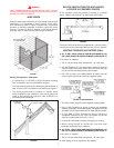
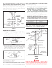
THESE MODELS ARE CERTIFIED FOR VERTICAL VENTING
AND SIDE WALL VENTING. THE UNIT CONSISTS OF AN INTAKE
VENT TERMINAL AND AN EXHAUST VENT TERMINAL WHICH
MUST BE USED TO TERMINATE THE VENTING ARRANGEMENT.
IF THE VENT TERMINALS SUPPLIED WITH THIS UNIT ARE
NOT USED TO TERMINATE THE VENTING ARRANGEMENT,
THE RISK OF IMPROPER OPERATION, FIRE, EXPLOSION, OR
ASPHYXIATION WILL INCREASE.