


8
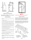
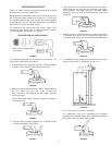
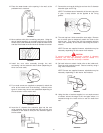
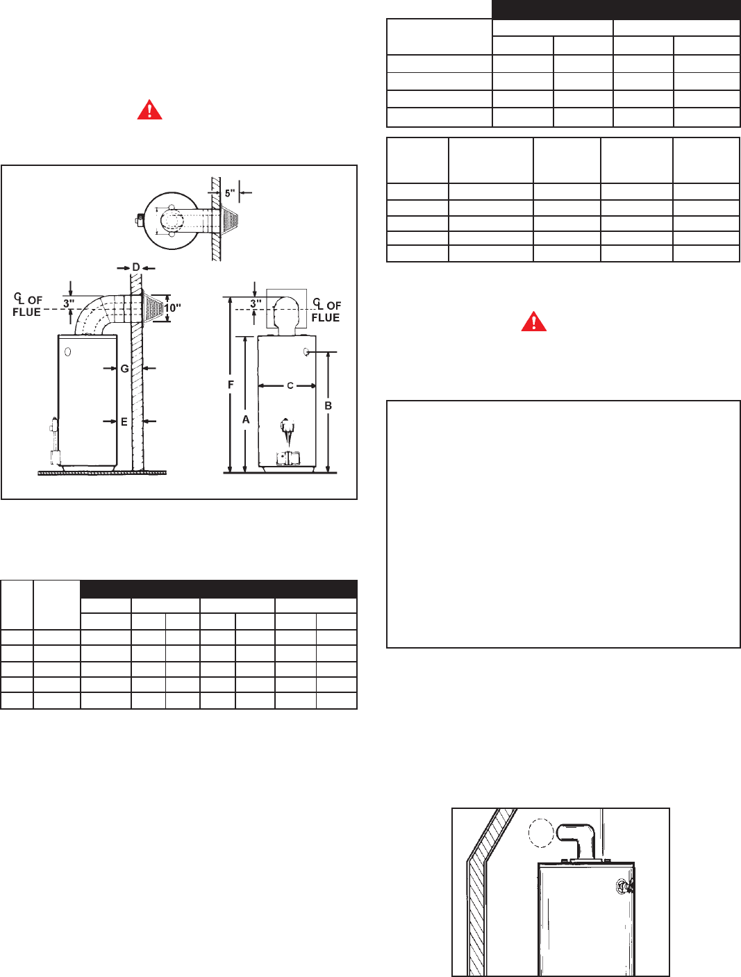
VERTICAL (EXTENSION KIT) HEIGHT
It is simple to determine which kit is needed for vertical height.
Take the total height (to the top of the flue) required and
comparing that to “F DIMENSION” in TABLE 1, it can be
determined which kit needs to be used vertically.
WARNING
Obstructions and deteriorated vent systems may present
serious health risk or asphyxiation.
FIGURE 12
TABLE 1.
* See models and rating plate attached to the water heater for
specific model number and other detailed information.
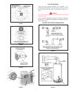
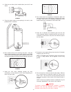
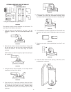
HORIZONTAL (EXTENSION KIT)
To determine the horizontal length and extension kit needed,
simply plug the dimensions
“
D” and “G” into the equation
below. The answer “E” should then be located in TABLE 2. The
size range in which “E” dimension falls indicates the kit that
should be used horizontally to obtain the desired length.
EQUATION: D + G = E
“D” = The wall thickness
“G” = The distance wanted between the edge of the water
heater and the inside edge of the wall
“E” = The distance the extension kit must be able to extend
TABLE 2.
*See models and rating plate attached to the water heater for
specific model number and other detailed information.
WARNING
Be sure vent pipe is properly connected to prevent escape of
dangerous flue gases which could cause deadly asphyxiation.
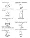
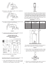
ALL INSTALLATIONS
For ease of assembly the installation of the various kit
combinations has been broken into individual sections.
The two steps below are common to all installations. Once
these have been performed, you need only to refer to the
type installation that pertains to you.
Installation Using Vent Kits:
1. Standard Vent Kit ..................................... Page 8
2. Optional Vertical Vent Kit ....................... Page 10
with Standard Vent Kit
3. Optional Horizontal Vent Kit ................... Page 13
4. Optional Horizontal and .......................... Page 15
Vertical Vent Kits
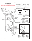
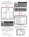
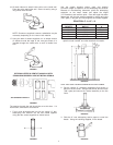
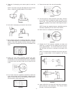
CUTTING THE OPENING THROUGH
THE OUTSIDE WALL
After thoroughly reading the “Locating the New Water Heater”
section of this manual and you have chosen a suitable water
heater installation site, use the chart below to determine
dimensions for the opening in the wall.
Cut a 6
1
/4” diameter hole completely through the outside wall.
FIGURE 13
BTU’s F DIMENSION
*GAL. in 1000’s900068-7 900124-6 900124-7 900124-8
CAP. NAT/L.P. STD. MIN. MAX. MIN. MAX. MIN. MAX.
40 36/36 63-3/4 72 77 77 88 88 110
50 38/38 72 80-3/4 86 86-1/4 97-1/4 97-1/4 118-3/4
40 40/40 63-3/4 72 77 77 88 88 110
50 48/44 76 84-1/4 89-3/4 89-3/4 100-3/4 100-3/4 122-3/4
75 55 NAT. 76-1/4 84-1/2 89-1/2 89-1/2 100-1/2 100-1/2 122-1/2
*BTU’S in
*GAL. 1000’s
CAP. NAT/L.P. A B C
40 36/36 48-3/4 41-3/4 21
50 38/38 57-1/2 50-1/2 21
40 40/40 48-3/4 41-3/4 21
50 48/44 61 54 21
75 55 NAT. 63 54-3/4 26-1/4
E DIMENSIONS
40-50 Gal. 75 Gal.
VENT KITS MIN. MAX. MIN. MAX.
900068-7-STD. 3-1/2 10 7/8 7-3/8
900124-6 10 15-1/2 7-3/8 12-7/8
900124-7 15-1/2 26-1/2 12-7/8 23-7/8
900124-8 26-1/2 48 23-7/8 45-3/8