


17
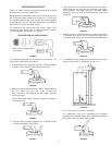
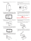
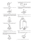
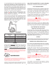
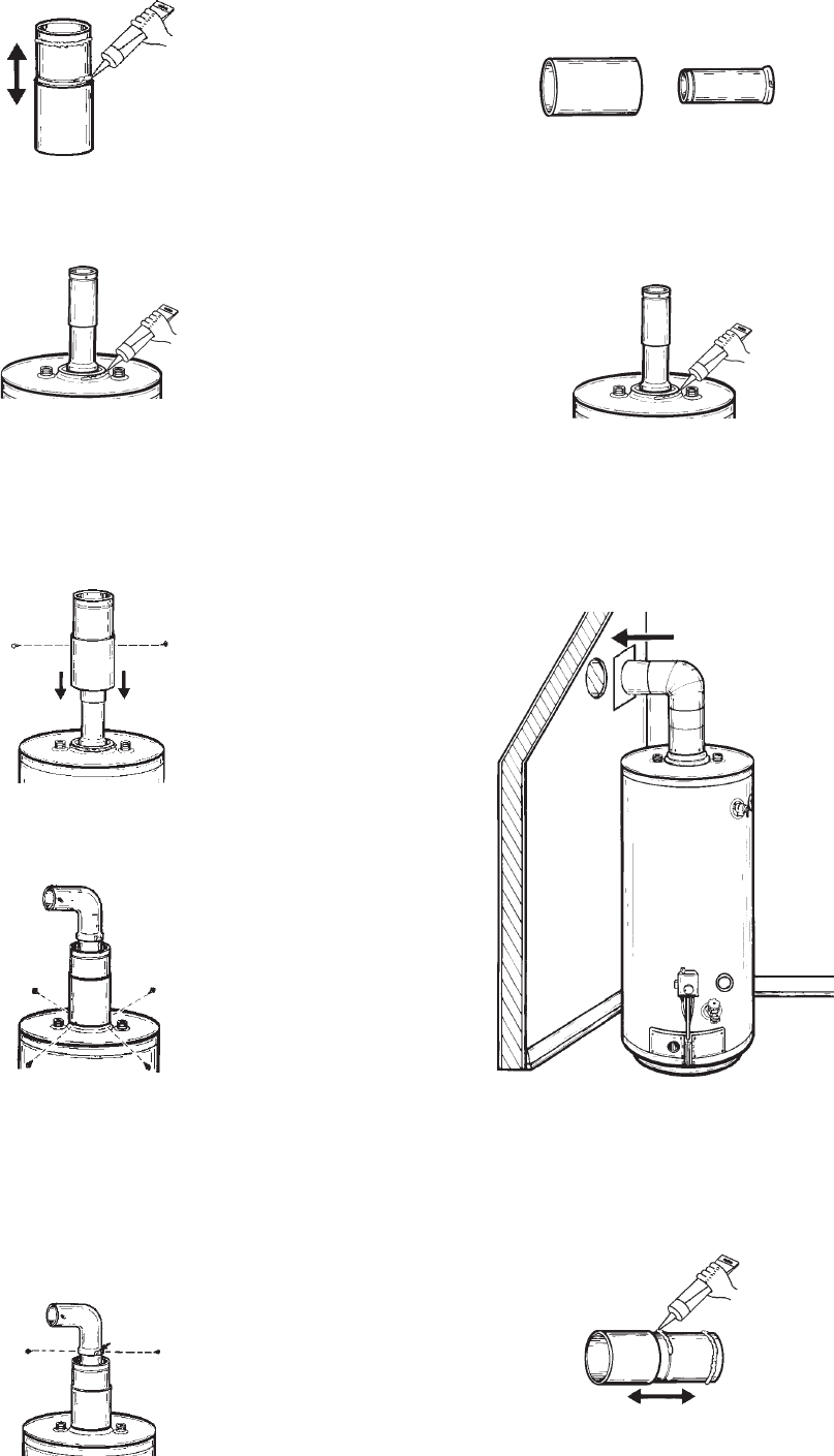
FIGURE 77
4. Using the tube of sealant supplied, run an ample amount
around the oval flare of the jacket.
FIGURE 78
5. Place the 6” vent section over the 3” flue section. Subtract
3/4” from the X dimension used earlier and this gives the
length of the 3” vent extension. Slide the 6” vent extension
apart to this dimension and lock it together using the two
screws supplied.
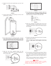
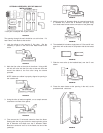
FIGURE 79
6. Bend the round end of the 6” vent extension oval at the
jacket tip and secure it using four sheet metal screws.
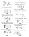
FIGURE 80
7. Place the 3” elbow on the flue extension.
NOTE: Make sure elbow is properly aligned to opening in
the outside wall.
Mark the 3” dia. end of the flue extension at the slots in the
elbow. Using a #22 drill bit, drill holes into the flue extension at
the two slots and secure the elbow to the flue extension using
the screws provided.
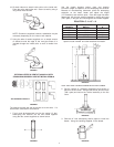
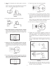
FIGURE 81
8. The standard kit includes a single piece of 3” flue and 6”
vent pipe which will not be used in conjunction with the
optional horizontal kit.
FIGURE 82
9. Making sure the 6” diameter elbow is centered around the
3” diameter flue, secure the 6” diameter vent pipe using
two sheet metal screws at the connection of the elbow and
6” vertical extension.
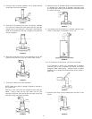
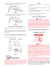
FIGURE 83
10. Slide the vent collar (to be installed later) over the 6” vent
elbow.
11. Place the water heater at the opening in the wall, at the
predetermined clearance.
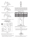
FIGURE 84
12. Slide the 6” telescoping vent section apart to reveal the
beads.
NOTE: The 6” pipe with beads will connect to the elbow.
Using the caulking supplied, fill the beads.
FIGURE 85
13. Insert the 6” telescoping vent section into the wall.