


21
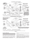
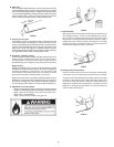
INSTALLATION OF VENT SYSTEM, SIDEWALL
With the route of the venting system and selection of materials completed,
as discussed in the section of this manual titled PLANNING THE VENT
SYSTEM, the through the wall vent terminal in place and the first section
of piping, up to first elbow, installed at the blower it is time to complete
the installation of the venting system for the sidewall installation.
FIGURE 20
Before completing the installation of the venting system be sure to read
the sections of this manual discussing the proper method of cutting
and cementing PVC pipe and fittings: VENT PIPE PREPARATION.
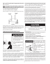
It is recommended that the completion of the venting system start at
the blower assembly and run to the coupling on the inside wall of
the vent terminal, Figure18.
The vent system piping should be supported every 5 feet (1.5 m)
of vertical run and every 3 feet (91 cm) of horizontal run. All piping
and fittings must be joined by the proper procedures as described
under: VENT PIPE PREPARATION.
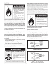
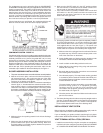
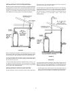
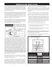
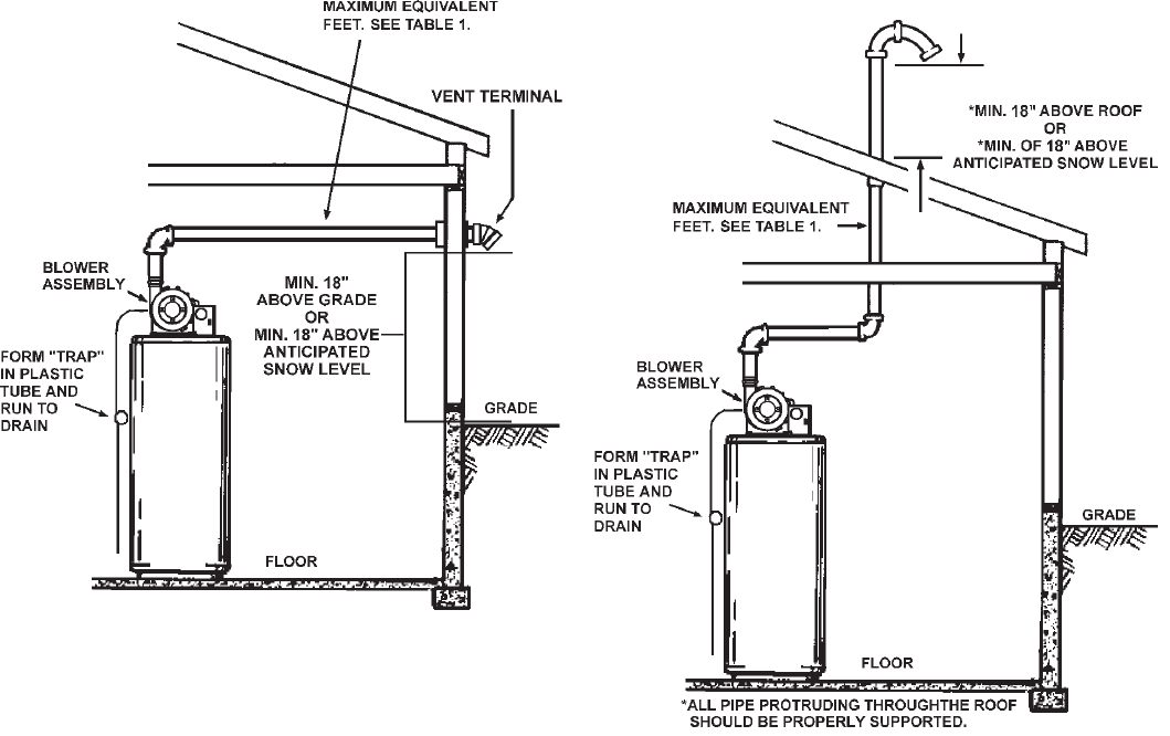
INSTALLATION OF VERTICAL VENT SYSTEM
A proper flashing or "BOOT" should be used to seal the pipe where
it exits the roof. The total vent system should not exceed the
equivalent feet of pipe as listed in Table 1.
Provide support for all pipe protruding through the roof. All piping
should be properly secured. The vent system piping should be
supported every 5 feet (1.5 m) of vertical run and every 3 feet (91
cm) of horizontal run. All piping and fittings must be joined by the
proper procedures as described under: VENT PIPE
PREPARATION.
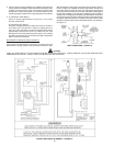
FIGURE 21
IMPORTANT
The vent system must terminate so that proper clearances are
maintained as cited in local codes or the current edition of the
National Fuel Gas Code (ANSI Z223.1) or the Natural Gas and
Propane Installation Code (CAN/CSA-B149.1) and as listed below:
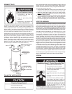
1. Vent Termination must extend a minimum of 18 inches (46 cm) above
roof or 18 inches (46 cm) above the anticipated snow level to prevent
blockage of the vent termination, as shown in Figures 20 and 21.