


16
FILLING THE WATER HEATER
Never use this water heater unless it is completely full of water.
To prevent damage to the tank, the tank must be fi lled with water.
Water must fl ow from the hot water faucet before turning “ON” gas
to the water heater.
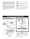
To fi ll the water heater with water:
1. Close the water heater drain valve by turning the handle to the
right (clockwise). The drain valve is on the lower front of the water
heater.
2. Open the cold water supply valve to the water heater.
NOTE: The cold water supply valve must be left open when
the water heater is in use.
3. To insure complete fi lling of the tank, allow air to exit by opening
the nearest hot water faucet. Allow water to run until a constant
fl ow is obtained. This will let air out of the water heater and the
piping.
4. Check all water piping and connections for leaks. Repair as
needed.
GAS PIPING
Make sure the gas supplied is the same type listed on the model
rating plate. The inlet gas pressure must not exceed 10.5” W.C.
for natural gas and 13” W.C. for propane (L.P.) gas. The minimum
inlet gas pressure shown on the rating plate is that which will permit
fi ring at rated input.
If the gas control valve/thermostat is subjected to pressures
exceeding 1/2 pound per square inch (3.5 kPa), the damage could
result in a fi re or explosion from leaking gas.
If the main gas line Shut-off serving all gas appliances is used, also
turn “off” the gas at each appliance. Leave all gas appliances shut
“off” until the water heater installation is complete.
A gas line of suffi cient size must be run to the water heater. Consult
the current edition of Natural Gas and Propane Installation Code
(CAN/CSA B149.1) and your gas supplier concerning pipe size.
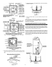
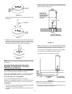
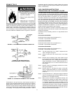
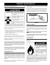
There must be:
• A readily accessible manual shut off valve in the gas supply line
serving the water heater, and
• A drip leg (sediment trap) ahead of the gas control valve/
thermostat to help prevent dirt and foreign materials from entering
the gas valve.
• A fl exible gas connector or a ground joint union between the shut
off valve and control valve to permit servicing of the unit.
Be sure to check all the gas piping for leaks before lighting the water
heater. Use a soapy water solution, not a match or open fl ame.
Rinse off soapy solution and wipe dry.
When installed at elevations above 4,500 feet (1371 m), input rating
should be reduced at the rate of 4 percent for each additional 1,000 feet
(305 m). This requires replacement of the burner orifice in
accordance with the Natural Gas and Propane Installation Code
(CAN/CSA B149.1-current edition). Contact your local gas supplier
for further information.
Failure to replace the standard orifi ce with a high altitude orifi ce
when installed could result in improper and ineffi cient operation of
the appliance, producing carbon monoxide gas in excess of safe
limits, which could result in serious injury or death. Contact your
gas supplier for any specifi c changes which may be required in
your area.
Use pipe joint compound or tefl on tape marked as being resistant
to the action of petroleum [Propane (L.P.)] gases.
The appliance and its gas connection must be leak tested before
placing the appliance in operation.
The appliance and its individual Shut-off valve shall be disconnected
from the gas supply piping system during any pressure testing of
that system at test pressures in excess of 1/2 pound per square inch
(3.5 kPa). It shall be isolated from the gas supply piping system
by closing its individual manual Shut-off valve during any pressure
testing of the gas supply piping system at test pressures equal to
or less than 1/2 pound per square inch (3.5 kPa).
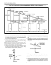
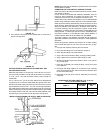
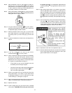
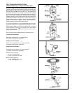
Connecting the gas piping to the gas control valve/thermostat of the
water heater can be accomplished by either of the two methods shown in
Figures 27, 28 and 29.