


13
the current building regulations should
be used. Installation should be carried
out generally as shown on the following
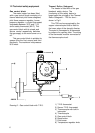
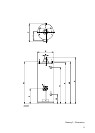
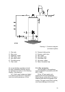
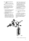
diagram. See drawing 4.
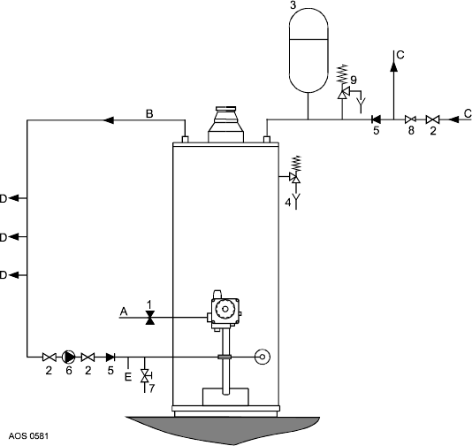
A.O. Smith water heaters are tested
to a maximum pressure of 12 bar and a
maximum working pressure of 8 bar.
1) Gas cock
2) Stop valve
3) Expansion vessel
4) T&P safety valve
5) Non return valve
6) Circulation pump
7) Drain valve
Drawing 4 - Connection diagram
(unvented system)
2.1.3 Gas connection
The gas supply to this appliance
must be installed in accordance with BS
6891 (1988).
Fit the 1/2" gas supply cock
supplied with this unit immediately
before the gas control block. No heat or
soldered joints should be applied in the
vicinity of the gas control block, as they
could cause damage to the control.
8) Pressure limiting valve
9) Pressure relief valve
A) Gas supply
B) Hot water outlet
C) Cold water inlet
D) Hot wayer outlets
E) Return circulation loop