


13
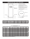
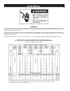
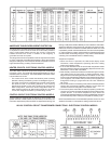
AMPERAGE TABLE/OVERCURRENT PROTECTION
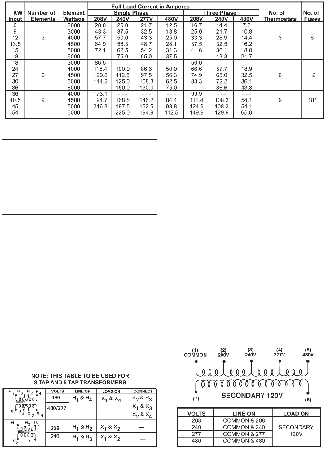
The tables above provides the total connected heating element load
in amperes for branch circuit conductor and overcurrent protection
sizing. Single-phase heaters are two wire circuits. Three-phase
heaters are three wire circuits. In addition to the foregoing, a
grounded conductor is required.
The rating of the overcurrent protection must be computed on the basis
of 125% of the total connected load amperage. Where the standard
ratings and settings do not correspond with this computation, the next
higher standard rating or setting should be selected.
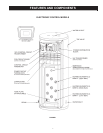
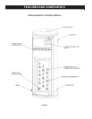
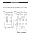
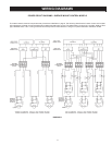
HEATER CIRCUITS - ELECTRONIC CONTROL MODELS
The water heater’s electrical components are pictured and identied
in Figures 1 and 2. The model and rating plate illustration on page 4
identies heater circuit ratings. The ELECTRONIC CONTROL model
has two electrical circuits.
• The control circuit, which controls the electrical power to heating
elements, referring the following control circuit diagram Figure 3.
• The power circuit, which is operated by the control circuit carries
the electrical load of the heating elements. The following
describes the heater circuits and includes wiring diagrams for
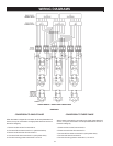
Delta conguration, refer to the “WYE Conguration Insert” for
water heaters operating at 380V/400V/416V/575V. All heater
circuits are designed for 50/60 cycle alternating current.
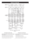
CONTROL CIRCUIT - ELECTRONIC CONTROL MODELS
These models are equipped with an electronic control system. The
system includes a CCB (Central Control Board) circuit board, an
immersion temperature probe with ECO for temperature sensing and
limiting, a UIM (User Interface Module) for user interface & information
display and element current sensors for monitoring the power circuits.
Refer to the control circuit label on the water heater for details. The CCB
is powered by a small 120V/24V transformer. The control circuit operates
on 120V supplied by a larger 100VA transformer. Standard equipment
includes control circuit fusing using two, 3 amp, class G fuses with 600
volt rating. Do not substitute fuses of a different rating.
Sequence of Operation
1. When the control is powered, the UIM should display model
information, water temperature, Operating Set Point, heating
status and operating mode.
2. If the control determines that the actual water temperature inside
the tank is below the programmed Operating Setpoint minus the (1st)
differential, a call for heat is activated.
3. After all safety checks are veried, the CCB will energize contactor
coils starting with the lower bank of heating elements (each
diagonal row of three heating elements is considered a “bank” - see
Figure 1) then energize the middle bank (if so equipped) and top bank
(if so equipped). The middle and top banks (if so equipped) are
energized according to programmed 2nd and 3rd differential
set points.
4. The control remains in the heating mode until the water temperature
reaches the programmed Operating Setpoint. At this point the
contactors will be de-energized in the reverse order.
5. The control system now enters the standby operating mode while
continuing to monitor the water temperature and the state of other
system devices. If the water temperature drops below the
programmed Operating Setpoint minus the (1st) differential, the control
will automatically return to step 2 and repeat the heating cycle.
NOTE: See the Electronic Control Models Operation section for more
detailed information on temperature settings mentioned above.
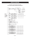
120 VAC CONTROL CIRCUIT TRANSFORMER CONNECTIONS - ELECTRONIC CONTROL MODELS