


11
manufacturer. The valve is certified by a nationally recognized
testing laboratory that maintains periodic inspection of production
of listed equipment of materials as meeting the requirements
for Relief Valves for Hot Water Supply Systems, ANSI Z21.22 •
CSA 4.4, and the code requirements of ASME.
If replaced, the new valve must meet the requirements of local
codes, but not less than a combination temperature and pressure
relief valve rated/sized and certified as indicated in the above
paragraph. The new valve must be marked with a maximum set
pressure not to exceed the marked hydrostatic working pressure
of the water heater (150 psi = 1,035 kPa) and a discharge
capacity not less than the water heater Btu/hr or KW input rate
as shown on the water heater’s model rating plate.
For safe operation of the water heater, the temperature and
pressure relief valve must not be removed from its designated
opening nor plugged. The temperature-pressure relief valve
must be installed directly into the fitting of the water heater
designed for the relief valve. Install discharge piping so that any
discharge will exit only within 6 inches (15.2 cm) above, or at any
distance below the structural floor. Be certain that no contact is
made with any live electrical part. The discharge opening must
not be blocked or reduced in size under any circumstances.
Excessive length, over 30 feet (9.14 m), or use of more than
four elbows can cause restriction and reduce the discharge
capacity of the valve.
No valve or other obstruction is to be placed between the relief
valve and the tank. Do not connect discharge piping directly to
the drain unless a 6” (15.2 cm) air gap is provided. To prevent
bodily injury, hazard to life, or property damage, the relief valve
must be allowed to discharge water in adequate quantities should
circumstances demand. If the discharge pipe is not connected
to a drain or other suitable means, the water flow may cause
property damage.
The Discharge Pipe:
• Shall not be smaller in size than the outlet pipe size
of the valve, or have any reducing couplings or other
restrictions.
• Shall not be plugged or blocked.
• Shall be of material listed for hot water distribution.
• Shall be installed so as to allow complete drainage of both the
temperature-pressure relief valve and the discharge pipe.
• Shall terminate at an adequate drain.
• Shall not have any valve or other obstruction between the relief
valve and the drain.
The temperature-pressure relief valve must be manually
operated at least once a year. Caution should be taken to
ensure that (1) no one is in front of or around the outlet of the
temperature-pressure relief valve discharge line, and (2) the
water manually discharged will not cause any bodily injury or
property damage because the water may be extremely hot. If
after manually operating the valve, it fails to completely reset
and continues to release water, immediately close the cold water
inlet to the water heater, follow the draining instructions in this
manual, and replace the temperature-pressure relief valve with
a properly rated/sized new one.
If you do not understand these instructions or have any questions
regarding the temperature-pressure relief valve call the toll free
number listed on the back cover of this manual for technical
assistance.
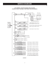
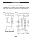
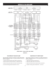
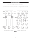
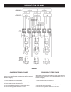
WATER LINE CONNECTIONS
This manual provides detailed piping installation diagrams (see
back section of this manual) for typical methods of application.
For the heater inlet and outlet connections, di-electric unions are
recommended. The water heater may be installed by itself, or with a
separate storage tank, on both single and two-temperature systems.
When used with a separate storage tank, the circulation may be either
by gravity or by means of a circulating pump. When a circulating
pump is used it is important to note that the ow rate should be slow
so that there will be a minimum of turbulence inside the heater.
CLOSED WATER SYSTEMS
Water supply systems may, because of code requirements or
such conditions as high line pressure, among others, have
installed devices such as pressure reducing valves, check valves,
and back flow preventers. Devices such as these cause the water
system to be a closed system.
THERMAL EXPANSION
As water is heated, it expands (thermal expansion). In a closed
system the volume of water will grow when it is heated. As the volume
of water grows there will be a corresponding increase in water pressure
due to thermal expansion. Thermal expansion can cause premature
tank failure (leakage). This type of failure is not covered under the limited
warranty. Thermal expansion can also cause intermittent temperature-
pressure relief valve operation: water discharged from the valve due to
excessive pressure build up. This condition is not covered under the
limited warranty. The temperature-pressure relief valve is not intended
for the constant relief of thermal expansion.
A properly sized thermal expansion tank should be installed
on all closed systems to control the harmful effects of thermal
expansion. Contact a local plumbing service agency to have a
thermal expansion tank installed.