


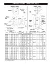

10
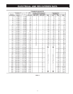
TABLE 1. BRANCH CIRCUIT WIRE SIZE.
These ampacities relate only to conductors
described in Table 310-13 of the NEC.
For ambient temperatures over 30°C, see
Correction Factors, Note 13 in the NEC.
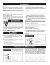
ELECTRICAL
GENERAL
Check the water heater model and rating plate information against
the characteristics of the branch circuit electrical supply. Do not
connect the heater to an improper source of electricity.
Voltage applied to the heater should not vary more than +5% to -10%
of the model and rating plate marking for satisfactory operation.
Do NOT energize the branch circuit for any reason before the water
heater tank is lled with water. Doing so may cause the heating
elements to fail.
The factory wiring is attached to a terminal block on the unit. The
branch circuit is connected to the block through an opening provided
on the heater. Factory terminal block has 500 MCM maximum copper
wire size capacity in each opening. If apparent eld wire size is over
500 MCM multiple terminal blocks will be furnished. If other opening
sizes are desired they should be specied when unit is ordered.
The installation must conform to these instructions and the local
code authority having jurisdiction. Grounding and electrical wiring
connected to the water heater must also conform to the National Electrical
Code, NFPA 70. This publication is available from The National Fire
Protection Association, 1 Batterymarch Park, Quincy, MA 02269.
BRANCH CIRCUIT
The branch circuit wire size should be established through reference
to the NEC (National Electrical Code) or other locally approved
sources in conjunction with the water heater amperage rating.. Wire
rated at 75°C should be used. For convenience, portions of the wire
size tables from the Code are reproduced in Table 1. It is suggested
the electrician size the branch circuit at 125 percent of the heater
rating and further increase wire size as necessary to compensate
for voltage drop in long runs. Voltage drop should not exceed 3%
at the water heater.
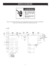
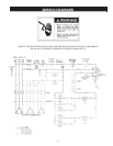
HEATER CIRCUITS
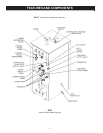
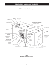
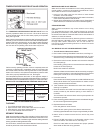
The water heater’s electrical components are pictured and identied
by the Features and Components illustrations on pages 6 and 7.
The model and rating plate illustration identies the heater electrical
characteristics. The heater has two electrical circuits:
Control Circuit: 120V circuit containing all safety and control devices.
The control circuit operates the contactors in the power circuit.
Power Circuit: High voltage, single or three phase circuit that carries
the heating element load.
The following section and pages describe the water heater circuits
and includes wiring diagrams.
CONTROL CIRCUITS
The heater is equipped with one of the following control circuits,
resulting in:
A. Thermostats (mechanical)... where all of the heating elements
are switched on/off by one or more thermostats. Heaters
with thermostat control are adjusted as described in TEMPERATURE
REGULATION section of this manual, see Page 14.
B. Step controlled element operation...where elements are staged
on/off individually or in groups rotationally by the controller.
An optional feature is modulation which operates in conjunction with
the staged on/off element operation.
C. Sequencer... operates in conjunction with a thermostat (mechanical).
The sequence is activated by a thermostat then the sequence
switches on the heater elements in 3 sequences (multiple elements
and contactors are required).
Additional instructional literature is provided with heaters equipped
with modulating solid state step control or a sequencer.
All control circuits are operated on single-phase 120 volt current.
Control circuit wiring is 14 Awg, AWM (Appliance Wiring Material)
type, rated 600 volts, 105°C.
Standard equipment includes control circuit fusing.
POWER CIRCUIT
Power circuit wiring is type THHN (or equivalent) rated 600 volts,
105°C, sized as necessary.
The following wiring diagrams are included in this manual to show
typical arrangements of electrical components in the control and power
circuits by voltage and phase characteristics. They are to be used as a
reference by the installer or servicer in performing their work. An actual
diagram of the water heater wiring is furnished with the heater.