


7
CARBONING OR SOOTING OF THE COMBUSTION CHAMBER,
BURNERS AND FLUE TUBES AND CREATES A RISK OF
ASPHYXIATION.
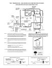
Where an exhaust fan is supplied in the same room with a
heater, sufficient openings for air must be provided in the walls.
UNDERSIZED OPENINGS WILL CAUSE AIR TO BE DRAWN INTO
THE ROOM THROUGH THE CHIMNEY, CAUSING POOR
COMBUSTION. SOOTING MAY RESULT IN SERIOUS DAMAGE
TO THE HEATER AND RISK OF FIRE OR EXPLOSION.
UNCONFINED SPACE
In buildings of conventional frame, brick, or stone construction,
unconfined spaces may provide adequate air for combustion,
ventilation and draft hood dilution.
If the unconfined space is within a building of tight construction
(buildings using the following construction: weather stripping,
heavy insulation, caulking, vapor barrier, etc.), air for combustion,
ventilation and draft hood dilution must be obtained from
outdoors. The installation instructions for confined spaces in
tightly constructed buildings must be followed to ensure
adequate air supply.
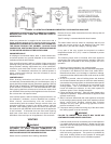
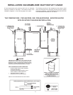
CONFINED SPACE
When drawing combustion and dilution air from inside a
conventionally constructed building to a confined space, such a
space shall be provided with two permanent openings, ONE IN
OR WITHIN 12 INCHES OF THE ENCLOSURE TOP AND ONE
IN OR WITHIN 12 INCHES OF THE ENCLOSURE BOTTOM.
Each opening shall have a free area of at least one square inch
per 1000 Btuh of the total input of all appliances in the enclosure,
but not less than 100 square inches.
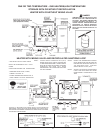
If the confined space is within a building of tight construction, air
for combustion, ventilation, must be obtained from outdoors.
When directly communicating with the outdoors or
communicating with the outdoors through vertical ducts, two
permanent openings, located in the above manner, shall be
provided. Each opening shall have a free area of not less than
one square inch per 4000 Btuh of the total input of all appliances
in the enclosure. If horizontal ducts are used, each opening
shall have a free area of not less than one square inch per
2000 Btuh of the total input of all appliances in the enclosure.
VENTING
WARNING
THE INSTRUCTIONS IN THIS SECTION ON VENTING MUST BE
FOLLOWED TO AVOID CHOKED COMBUSTION OR
RECIRCULATION OF FLUE GASES. SUCH CONDITIONS CAUSE
SOOTING OR RISKS OF FIRE AND ASPHYXIATION.
Heater must be protected from freezing downdrafts.
Remove all soot or other obstructions from the chimney that will
retard a free draft.
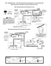
Type B venting is recommended with these heaters.
This water heater must be vented in compliance with all local
codes, the current revision of the National Fuel Gas Code
(ANSI-Z223.1) and with the Category I Venting Tables.
If any part of the vent system are exposed to ambient
temperatures below 40°F (4°C) it must be insulated to prevent
condensation.
The following steps shall be followed with each appliance
connected to the venting system placed in operation, while any
other appliances connected to the venting system are not in
operation.
1. Seal any unused openings in the venting system.
2. Inspect the venting system for proper size and horizontal pitch,
as required in the National Fuel Gas Code, ANSI Z223.1.
Determine that there is no blockage or restriction, leakage,
corrosion and other deficiencies which could cause an unsafe
condition.
3. So far as is practical, close all building doors and windows
and all doors between the space in which the water heater(s)
connected to the venting system are located and other spaces
of the building. Turn on all appliances not connected to the
venting system. Turn on all exhaust fans, such as range
hoods and bathroom exhausts, so they shall operate at
maximum speed. Close fireplace dampers.
4. Follow the lighting instruction. Place the water heater being
inspected in operation. Adjust thermostat so appliance shall
operate continuously.
5. After it has been determined that each appliance connected
to the venting system properly vents when tested as outlined
above, return doors, windows, exhaust fans, fireplace
dampers and any other gas burning appliance to their
previous conditions of use.
6. If improper venting is observed during any of the above tests,
the venting system must be corrected.
WARNING
FAILURE TO CORRECT BACK DRAFTS MAY CAUSE AIR
CONTAMINATION AND UNSAFE CONDITIONS.
• If the back draft cannot be corrected by the normal method or
if a suitable draft cannot be obtained, a blower type flue gas
exhauster must be employed to assure proper venting and
correct combustion.
• Do not connect the heater to a common vent or chimney with
solid fuel burning equipment. This practice is prohibited by
many local building codes as is the practice of venting gas
fired equipment to the duct work of ventilation systems.
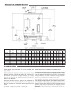
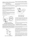
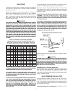
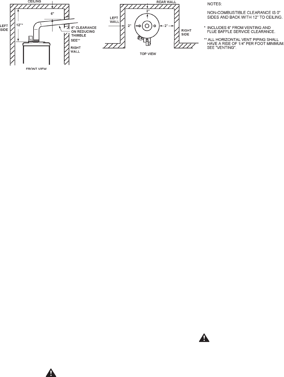
FIGURE 6 - ILLUSTRATION OF MINIMUM COMBUSTIBLE CLEARANCES IN AN ALCOVE