


21
NOTE:
1. Remove main burners from unit.
2. Check that burner venturi and ports are free of foreign debris.
3. Clean burners with bristle brush and/or vacuum cleaner
- DO NOT distort burner ports or pilot location.
4. Reinstall burners in unit. Make sure front and rear of burners
are installed correctly in burner support brackets.
Also check for good flow of combustion and ventilating air to the
unit. Maintain a clear area around the heater at all times.
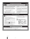
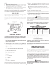
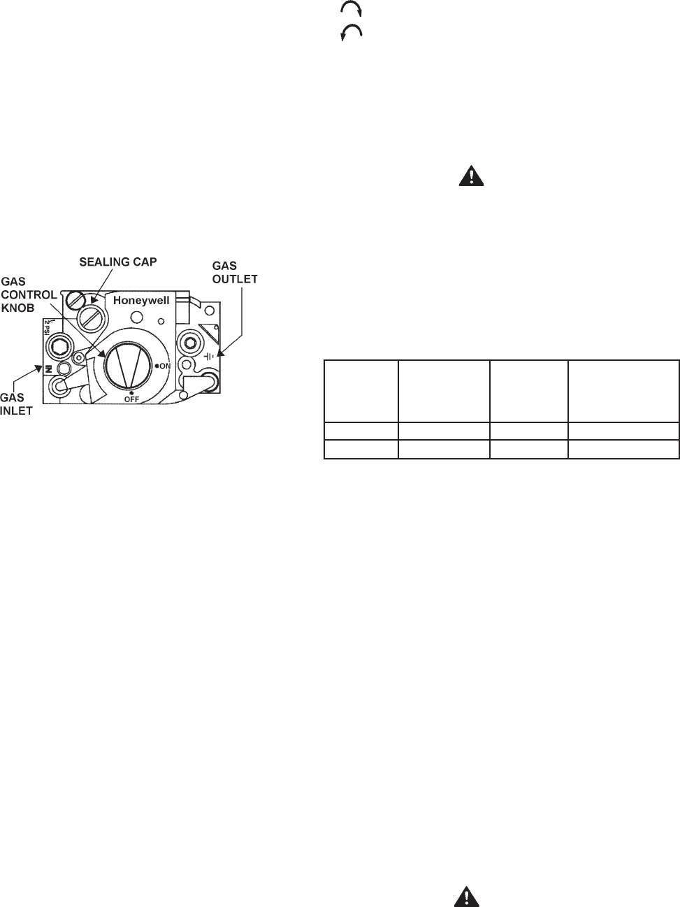
GAS VALVES
Figure 13 shows the type of combination manual gas control
valve and regulator used on these heaters.
If the gas valve becomes defective, repairs should not be
attempted. A new valve should be installed in place of the defective
one.
FIGURE 13
CHECKING THE INPUT
For appliance installation locations with elevations above
2000 feet, refer to HIGH ALTITUDE INSTALLATIONS section of
this manual for input reduction procedure.
1. Attach a pressure gauge or a manometer to the gauge port
and refer to the GAS PRESSURE REGULATOR section for
correct manifold pressure.
2. Use this formula to “clock” the meter. Be sure that other gas
consuming appliances are not operating during this interval.
3600 X H = Btuh
T
T = Time in seconds to burn one cubic foot of gas.
H = Btu’s per cubic foot of gas.
Btuh = Actual heater input.
Example:
T = 15.1 seconds
H = 1050 Btu
Btuh = ?
19 X 1050 = 199,999 Btuh
Should it be necessary to adjust the gas pressure to the burners
to obtain the full input rate, the steps below should be followed:
3. Remove the regulator adjustment sealing cap, see
Figure 13, and adjust the pressure by turning the adjusting
screw with a screwdriver.
Clockwise to increase gas pressure and input rate.
Counterclockwise to decrease gas pressure and input
rate.
4. “Clock” the meter as in step 2 above.
5. Repeat steps 3 and 4 until the specified input rate is achieved.
6. Turn the gas control knob to PILOT. Remove the pressure
gauge and replace the sealing cap and the allen wrench set
screw in the pressure tap opening.
WARNING
UNDER NO CIRCUMSTANCES SHOULD THE GAS INPUT EXCEED
THE INPUT SHOWN ON THE HEATER MODEL AND RATING
PLATE. OVERFIRING COULD RESULT IN DAMAGE OR SOOTING
OF THE HEATER.
When the heater is operating at full capacity, or full gas input, it
should consume 1 cu. ft. of gas in time indicated on Table 3.
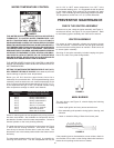
TABLE 3
APPROXIMATE TIME REQUIRED TO CONSUME
1 CU. FT. OF GAS AT FULL CAPACITY
TIME REQ’D
INPUT TYPE BTUH TO CONSUME
RATE OF PER 1 CU. FT.
(BTUH) GAS CU. FT. OF GAS
154,000 NATURAL 1050 24.5 SEC.
199,000 NATURAL 1050 19.0 SEC.
Figures shown are valid for 0-2000 ft.(0-610m) installations.
See “HIGH ALTITUDE INSTALLATIONS” for deration
requirements over 2000 ft.(610m).
VENTING SYSTEM
Examine the venting system every six months for obstructions
and/or deterioration of the vent piping.
Remove all soot or other obstructions from chimney which will
retard free draft.
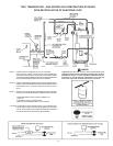
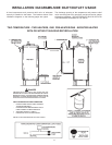
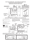
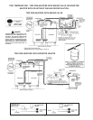
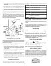
REMOTE STORAGE TANK
TEMPERATURE CONTROL
The water temperature in the storage tank (if used) is controlled
by the storage tank temperature control. The sensing element
is mounted in the hot water storage tank, see page 17.
A change in water temperature in the storage tank lower than the
tank temperature control setting will cause the sensor to activate
the circulating pump. The pump then circulates the water through
the heater where the thermostat senses the drop in water
temperature and activates main burner operation of the appliance.
If the storage tank temperature control is out of calibration, replace
with new control.
WARNING
SHOULD OVERHEATING OCCUR OR THE GAS SUPPLY FAIL TO
SHUT OFF, TURN OFF THE MANUAL GAS CONTROL VALVE TO
THE APPLIANCE.