


18
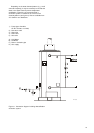
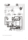
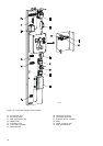
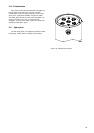
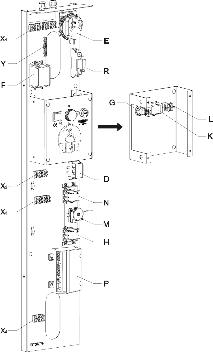
Figure 13 - Connection diagram control-column.
D) Transformer 230
E) Air proving switch
F) EMC single phase filter
G) RESET knob
H) Thermostat frost
K) Thermostat regulation
L) Switch ON/OFF
M) Thermostat overheat
N) Thermostat high limit
P) Automatic burner controller
R) Relay
X) Plastic connector strip
Y) Earth terminal block
IMD-0063