


4
the surrounding air pressure. Inspection of the boiler and vent
system is necessary to insure that flue gas leakage to the
surrounding area does not occur.
Inspect the external surfaces of the vent system every 3 months
for corrosion and leakage. Inspect the vent terminations for
corrosion and foreign matter which may be blocking the
exhausting flue products. Call a qualified service agent to
replace or repair any corroded or leaking parts.
A qualified service agent must inspect the internal surfaces of
the vent system and the boiler at least once a year.
BURNER SYSTEM
To maintain safe operation and the greatest efficiency for the
boiler, observe the burner flame through the observation port on
the jacket panel, once a month for proper flame characteristics.
• The burners should display the following characteristics:
• Provide complete combustion of gas.
• Cause rapid ignition and carry over across all burners and
across the entire burner.
• Give quiet operation during ignition, burning and extinction.
• Cause no excessive lifting of flames from the burner ports.
If the preceding characteristics are not evident, check for
accumulation of lint or other foreign material that restricts the
inlet air or burner ports. Ensure there is the proper amount of air
to the burner. Flame lifting from the burner is caused by too
much air to the burner.
The burners must be inspected by a qualified service technician
at least once a year.
DO NOT STORE COMBUSTIBLE MATERIALS, GASOLINE, OR
OTHER FLAMMABLE VAPORS, LIQUIDS IN THE AREA OF THE
APPLIANCE. NONCOMPLIANCE MAY RESULT IN FIRE OR
EXPLOSION. DO NOT OBSTRUCT THE FLOW OF
COMBUSTION OR VENTILATION AIR TO THE APPLIANCE.
CHEMICAL VAPOR CORROSION
Boiler corrosion and component failure can be caused by
airborne chemical vapors. Spray can propellants, cleaning
solvents, refrigerants, calcium or sodium chloride (water softener
salts), waxes, and process chemicals are typical compounds
that are potentially corrosive. These materials are corrosive at
very low concentration levels with little or no odor to reveal their
presence. Products of this sort should not be stored near the
boiler. Air which is brought in contact with the boiler should not
contain any of these chemicals. The boiler should be provided
with air from outdoors when installed in environments having
corrosive atmospheres.
CIRCULATION PUMP
Refer to the pump manufacturer's schedule of maintenance for
frequency and method of lubricating the pump and motor. Inspect
the pump once a month for leaky mechanical seals and/or
O-rings and loose or damaged components. Contact a qualified
service agent to replace or repair parts as required.
ELECTRONIC HOT SURFACE
IGNITION CONTROL BOARD
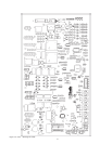
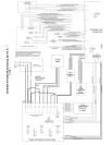
The EMC5000 control system is a fully integrated, state of the art
electronic control system. It consists of sensors, output devices,
a power switch, a 24vac transformer, wiring, and the following
printed circuit boards:
Central Control Board (CCB). See Figure 1A.
Flame Control Board (FCB). See Figure 1B.
User Interface Board (UIB). This part of the User Interface
Module (UIM). See Figure 3.
Power Distribution Board (PDB). See Figure 1C.
Touch Sensor Board (TSB). This is part of the User
Interface Module (UIM). See
Figure 3.
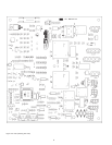
The CCB contains circuitry for both master control and flame
control for the first stage. The FCB contains circuitry for flame
control on up to one additional stage. Dip switches on the CCB
and FCB are used to configure the system. The UIB and TSB
are included in the User Interface Module (UIM) along with a 4
line by 20-character LCD display. The PDB provides connection
points for input power, the water pump, and the transformer. It
also distributes power to the system and contains the system
fuses.
Dual stage control is accomplished by means of an internal
communication network and the FCB's. One FCB is required for
each stage beyond initial first stage. The CCB also contains an
external communications system to allow for connection to a
PC, a modem, or an EMS system. Through this connection
multiple boilers can also be linked together.
CAUTION
The internal communications cables should never be connected
to the external communications connectors and vice-versa.
There are several microcontrollers used on the board. Three on
the CCB, two on the FCB, and one on the UIB. These micros
control the temperature and ignition control functions for the
boiler. Inherent in the design are the normal operating sequences
and safety features associated with a gas ignition control system.
The system continuously performs various diagnostic tests to
verify proper appliance and control operation. Should an unsafe
condition occur, the control will shut down the burner and display
a red fault light as well as indicate the cause of the fault on the
display. The operating programs for the system are stored in
permanent memory inside the micros. User-selectable
operating parameters and a history of detected faults are stored
in re-writable memory in the micros. A loss of power does not
affect either of the memories.
Inputs To CCB and FCB:
• Temperature Sensors:
• Temperature probes (CCB - outlet and either inlet or tank is
required): The CCB accepts analog temperature inputs from
up to three sensors (inlet, outlet and tank).
• ECO input (CCB - required):
The ECO (Energy Cut-Off) is a Hi-Limit switch, which is
located inside the output probe. It is a normally closed switch
that opens if the probe is exposed to a temperature higher
than the trip point.
• Thermostat input (CCB - optional):
This input is set up to work with an externally connected
thermostat that provides a contact closure. If this input is