


11
The operation of these parts is described below:
UIM Screens:
On all screens a double vertical bar appears on the right side of
the display each time a key is touched to indicate that a key has
been activated. On several screens an indicator ">" appears on
the left side of the display to indicate the active line. The "Up/
Down" keys are used to move the indicator to the desired line
and the "Select" key is pressed to select the line. Also, on most
of the screens, up/down arrows appear on the right side of the
screen to indicate that there are additional lines either above or
below the displayed four lines.
• Menu Screen:
Displayed when the user presses the "Menu" key. This screen
is the selection point for the other 9 screens.
• Temperature Screen:
Displays the sensed temperatures of the Outlet, Inlet, and
Tank probes. Also displayed is the calculated Delta T (Outlet
minus Inlet) for the system. Shorted ("Short") and
disconnected ("----") probes are also displayed.
• System Status Screen:
This screen is used to view the status of switch inputs and
output states. An asterisk (*) is displayed next to the label
when the status is "True" (the description is fulfilled). For
example, if water is flowing, or detected by the flow sensor,
then an "*" will appear in front of the Flow label (i.e. *Flow).
Another example would be the ECO switch. If the outlet
temperature is too high the display will show: *ECO.
NOTE: The LW/CO, IRI Gas Valve, Powered Vent, High Gas, and
Low Gas inputs are optional inputs. Flame sensing, Igniters,
and Blowers are optional on Stages 2, 3 and 4. (Except on a 4-
stage system, stage 2 always has an Igniter, Blower, and Flame
Sensor. Those dipswitches on stage 2 are not relevant.) One or
two speed blowers can be used on any stage.
The System monitors the inputs at these times:
• ECO, LW/CO, Blocked Flue, Low Gas, Hi Limit, and Hi Gas -
at all times for a fault condition.
• Tstat - at all times for open/closed conditions.
• IRI Gas and Powered Vent - for an on condition when their
respective outputs (Pump, IRI Gas Pwr, Powered Vent Power)
are turned on and an off condition at all other times.
• Flow - for an on condition when the pump is on (no check for
off state)
• High Speed Blower Prover - when the High Speed Blower is
on.
• Low Speed Blower Prover - when either the High or Low Speed
Blowers are on.
• Igniter Current - for an on condition approximately 18 seconds
after the Igniter is turned on until the igniter is turned off and
an off condition at all other times.
• Flame - for an on condition approximately 5 seconds after the
gas valve is turned on until the valve is turned off and at all
other times for an off condition.
Control Status Screen:
Displays the software that the CCB and FCB micros are in. The
CCB has 8 possible states and the FCB's have 9. The normal
CCB states sequence is to move from Idle, to Pre-Circulate,
then to Heating Stage 1-4 when a call for heat is initiated. Once
heat has been satisfied or the Total is opened, the sequence
moves to Post-Circulate and then back to Idle. If a fault occurs at
any time, the process jumps out of sequence and goes directly
to the appropriate Hard or Soft Fault state.
Description of CCB control states:
• Idle:
The yellow "Standby" LED is turned on and the system waits
for a heat request (determined by the Thermostat and
controlling probe inputs). All outputs are off in this state except
that if the Post-Circulate time is set to continuous the pump
will be on. When the heat request is received, the system
moves to the Pre-Circulate state.
• Pre-Circulate:
The yellow LED is turned off and the green "Running" LED is
turned on. The green LED will remain on for all other states
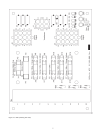
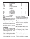
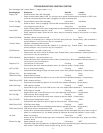
The folllowing status information is displayed from this screen:
Status Displayed *(True Condition) Input Output
ECO Outlet temperature too high open - - - -
LW/CO Water Level low open - - - -
Blk Flue Flue blocked open - - - -
Flow Water flowing closed - - - -
Low Gas Gas pressure low open - - - -
Tstat Thermostat requesting heat closed - - - -
Hi Limit Outlet temp exceeds High Limit setpoint - - - - - - - -
Pump Pump output activated - - - - On
IRI Gas Pwr IRI output relay activated - - - - On
IRI Gas IRI Gas Valve on closed - - - -
Pwr Vent Power Vent running closed - - - -
Alarm Alarm output activated - - - - On
Pwr Vent Pwr Power Vent output relay activated - - - - On
- - - - STAGES 1 to 4 - - - -
BlwHi Prv Blower pressure sufficient closed - - - -
Blw Hi Blower High output activated - - - - On
BlwLo Prv Blower pressure sufficient closed - - - -
Blw Lo Blower low output activated - - - - On
Ignt Cur Igniter current sufficient for ignition - - - - - - - -
Ignit Igniter output is activated - - - - On
Gas Relay Gas output relay activated - - - - On
Hi Gas Gas pressure too high open - - - -
Flame Flame detected - - - - - - - -