17
SEDIMENT TRAPS
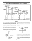
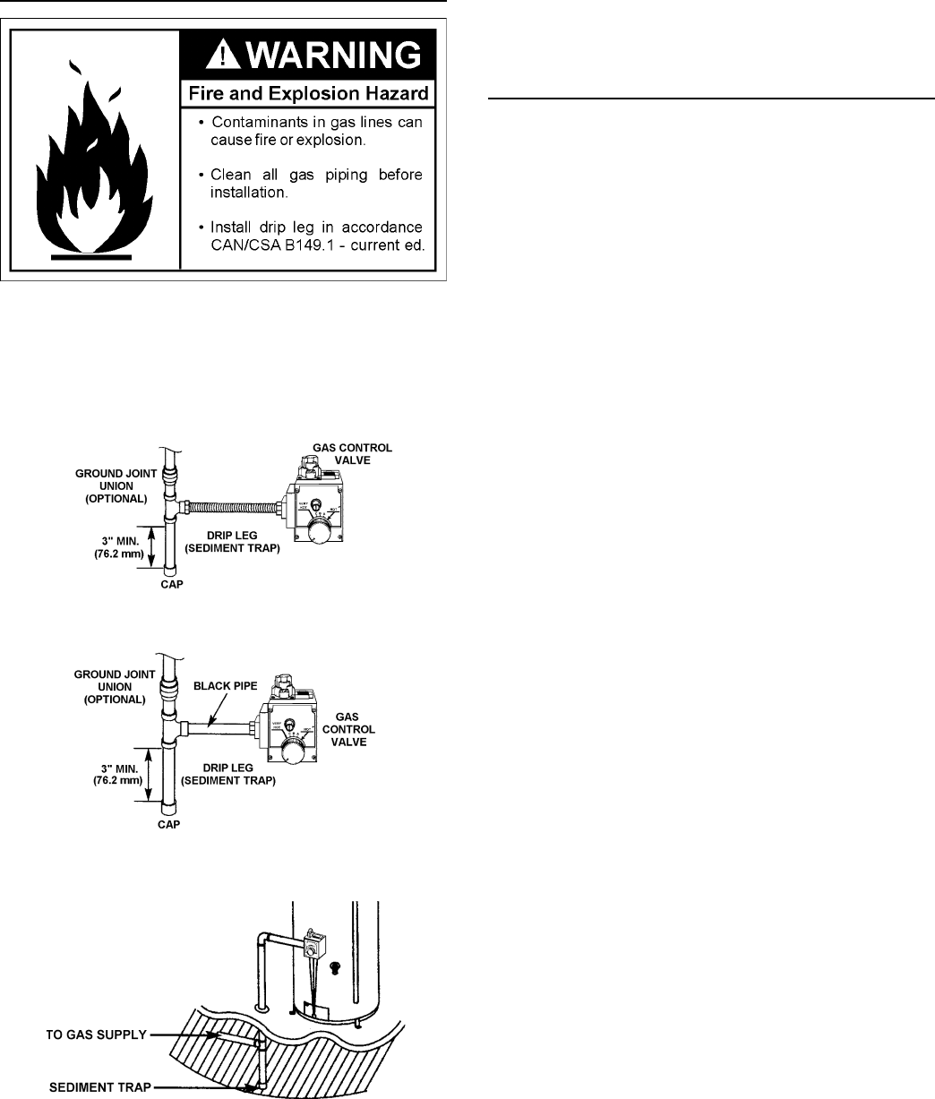
A sediment trap shall be installed as close to the inlet of the water
heater as practical at the time of water heater installation. The
sediment trap shall be either a tee fi tting with a capped nipple in the
bottom outlet or other device recognized as an effective sediment
trap. If a tee fi tting is used, it shall be installed in conformance with
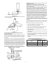
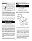
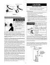
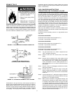
one of the methods of installation shown in Figures 27, 28 and 29.
FIGURE 27. GAS PIPING WITH FLEXIBLE CONNECTOR.
FIGURE 28. GAS PIPING WITH ALL
BLACK IRON PIPE TO GAS CONTROL.
FIGURE 29. ALTERNATIVE SEDIMENT TRAP LOCATION
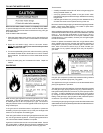
Contaminants in the gas lines may cause improper operation of
the gas control valve/thermostat that may result in fi re or explosion.
Before attaching the gas line be sure that all gas pipe is clean on
the inside. To trap any dirt or foreign material in the gas supply line,
a drip leg (sometimes called a sediment trap) must be incorporated
in the piping. The drip leg must be readily accessible. Install in
accordance with the “Gas Piping” section. Refer to the current
edition of the Natural Gas and Propane Installation Code (CAN/CSA
B149.1-current edition).
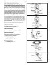
FUEL CONVERSION INSTRUCTIONS
FROM NATURAL GAS TO PROPANE (L.P.) GAS
This water heater has been factory equipped to operate with the
type gas indicated in the “EQUIPPED FOR” area of the model rating
plate located near the gas control valve/thermostat. The indicated
gas may be either Natural or Propane (L.P.). By following the
conversion instructions in this manual or the instructions near the
gas control valve/thermostat, the water heater must be converted if
it is to be used with the opposite gas. DO NOT USE THIS WATER
HEATER WITH ANY GAS OTHER THAN THE ONE LISTED ON
THE MODEL RATING PLATE. Failure to use the correct gas can
cause problems which can result in DEATH, SERIOUS BODILY
INJURY, OR PROPERTY DAMAGE. If you have any questions or
doubts consult your gas supplier or gas company.
Read and follow detailed conversion instructions located on the
water heater and also in the instruction manual in their entirety before
starting the conversion.
Conversion kit with necessary parts are in a bag attached to the
drain valve.
FOR 30 GALLON HEATER:
Orifi ce size: #40 for Natural / #52 for Propane (L.P.),
if converted - Propane Rate: 30,000 BTU.
FOR 40 GALLON HEATER:
Orifi ce size: #38 for Natural / #51 for Propane (L.P.),
if converted - Propane Rate: 32,000 BTU.
FOR 50 GALLON HEATER:
Orifi ce size: #35 for Natural / #51 for Propane (L.P.),
if converted - Propane Rate: 38,000 BTU.
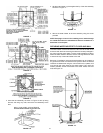
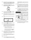
Step 1. Turn gas control knob “A” to “PILOT”. Depress and turn
“OFF”, see Figure 30 page 19.
Step 2. Remove outer and inner access doors from water
heater.
Step 3. Remove burner assembly from water heater control
by fi rst removing 6 screws holding inner door to heater,
then loosening 3/4” nut “H” holding burner assembly to
control, see fi gures 31 and 32. Loosen pilot tube nut “J”
and thermocouple nut “K” at control. Disconnect wire to
Piezo Igniter.
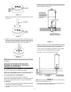
Step 4. Remove screws “D” disengaging manifold from burner,
see Figure 33 page 19.
Step 5. Remove orifi ce “E”, see Figure 34 page 19 using 3/8”
wrench. Install orifi ce marked “L.P.” found in the bag into
manifold. Tighten securely. Secure burner to manifold with
screws “D”.
Step 6. Loosen pilot tube nut “F”, see Figure 34 page 19. Remove
orifi ce “G” and replace with red colored orifi ce found in bag.
Reinstall nut “F” and tighten securely.
Step 7. Make sure all connections are tightened securely, and
reinstall burner assembly into water heater. Position end
of manifold inside bracket as shown in Figure 33 page
19. Reinstall manifold into control and tighten 3/4” nut
(“H”) securely. Recheck to see that end of manifold is still
inside bracket as shown in Figure 33 page 19. Reinstall
pilot tubing and thermocouple into control, see Figure 31
page 19. Connect wire to Piezo Igniter. Reinstall inner door
using the 6 screws removed in Step 3.


