34
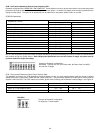
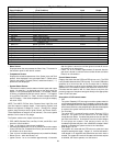
TABLE 20. RISK OF SCALDS.
TEMPERATURE TIME TO PRODUCE 2nd & 3rd
SETTING DEGREE BURNS ON ADULT SKIN
OVER 170°F (77°C) NEARLY INSTANTANEOUS
160°F (71°C) ABOUT 1/2 SECOND
150°F (66°C) ABOUT 1-1/2 SECONDS
140°F (60°C) LESS THAN 5 SECONDS
130°F (54°C) ABOUT 30 SECONDS
120°F (49°C) OR LESS MORE THAN 5 MINUTES
USE ANTI-SCALD VALVE(S) in the hot water system to reduce the
risks of scalding at points of use such as lavatories, sinks and
bathing facilities.
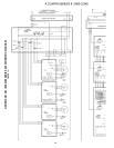
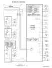
CONTROL SYSTEM
The EMC 5000 control system is a fully integrated, state of the art
electronic control system. It consists of sensors, output devices, a
power switch, a 24vac transformer, wiring and the following printed
circuit boards:
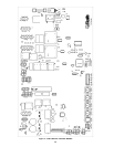
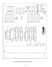
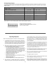
• Central Control Board (CCB), see Figure 17.
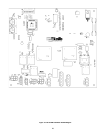
• Flame Control Board (FCB), see Figure 18.
• Power Distribution Board (PDB), see Figure19.
• User Interface Module (UIM), see Figure 21.
The CCB contains circuitry for both master control and flame control
for the first stage. The FCB's contains circuitry for control on up to
three additional stages. Dipswitches on the CCB and FCB are used
to configure the system. The User Interface Module (UIM)
communicates with the user through a set of touch pads and a 4-
line, 20-character LCD display. The PDB provides connection points
for input power, the water pump, and the transformer. It also
distributes power to the system and contains the system fuses.
Multiple-stage control is accomplished by means of an internal
communications network between the CCB and the FCB's. One
FCB is required for each stage beyond the initial first stage. The
CCB also contains an external communications system to allow
for connection to a PC, a modem, an EMS system, or something
similar. Through this connection multiple boilers can also be linked
together. CAUTION: The internal communications cables should
never be connected to the external communications connectors
and vice-versa.
There are several microcontrollers used on the boards. These
micros control the temperature and ignition control functions for
the boiler. Inherent in the design are the normal operating
sequences and safety features associated with a gas ignition
control system. The system continuously performs various
diagnostic tests to verify proper appliance and control operation.
Should an unsafe condition occur, the control will shut down the
burner and display a red fault light as well as indicate the cause of
the fault on the display. The operating programs for the system are
stored in permanent memory inside the micros. User-selectable
operating parameters and a history of detected faults are stored in
re-writable memory in the micros. A loss of power does not affect
either of the memories.
Inputs to CCB and FCB
Temperature Sensors:
• Temperature probes (CCB - outlet and either inlet or tank are
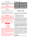
MANIFOLD PRESSURE
The manifold gas pressure is measured at the pressure tap on the
downstream side of the combination gas valve(s). For natural gas
the Manifold Pressure should measure 3.5" W.C. For propane (LP)
gas, the pressure should read 10" W.C.
IMPORTANT
UNDER NO CIRCUMSTANCES SHALL THE GAS PRESSURE
MEASURED AT THE BURNER MANIFOLD EXCEED THAT STATED
ON THE BOILER RATING PLATE. OVERFIRING WILL RESULT IN
DAMAGE TO THE BOILER, AS WELL AS INCREASED RISK OF
FIRE, SOOTING AND ASPHYXIATION.
ADJUSTMENTS
ON INITIAL STARTUP SOME ADJUSTMENTS ARE NECESSARY.
1. CHECK MANIFOLD AND INLET GAS PRESSURES.
2. CHECK THE INPUT. SEE NATIONAL FUEL GAS CODE, ANSI
Z223.1 OR CAN/CSA - B149.1 (CURRENT EDITION) FOR
PROCEDURES.
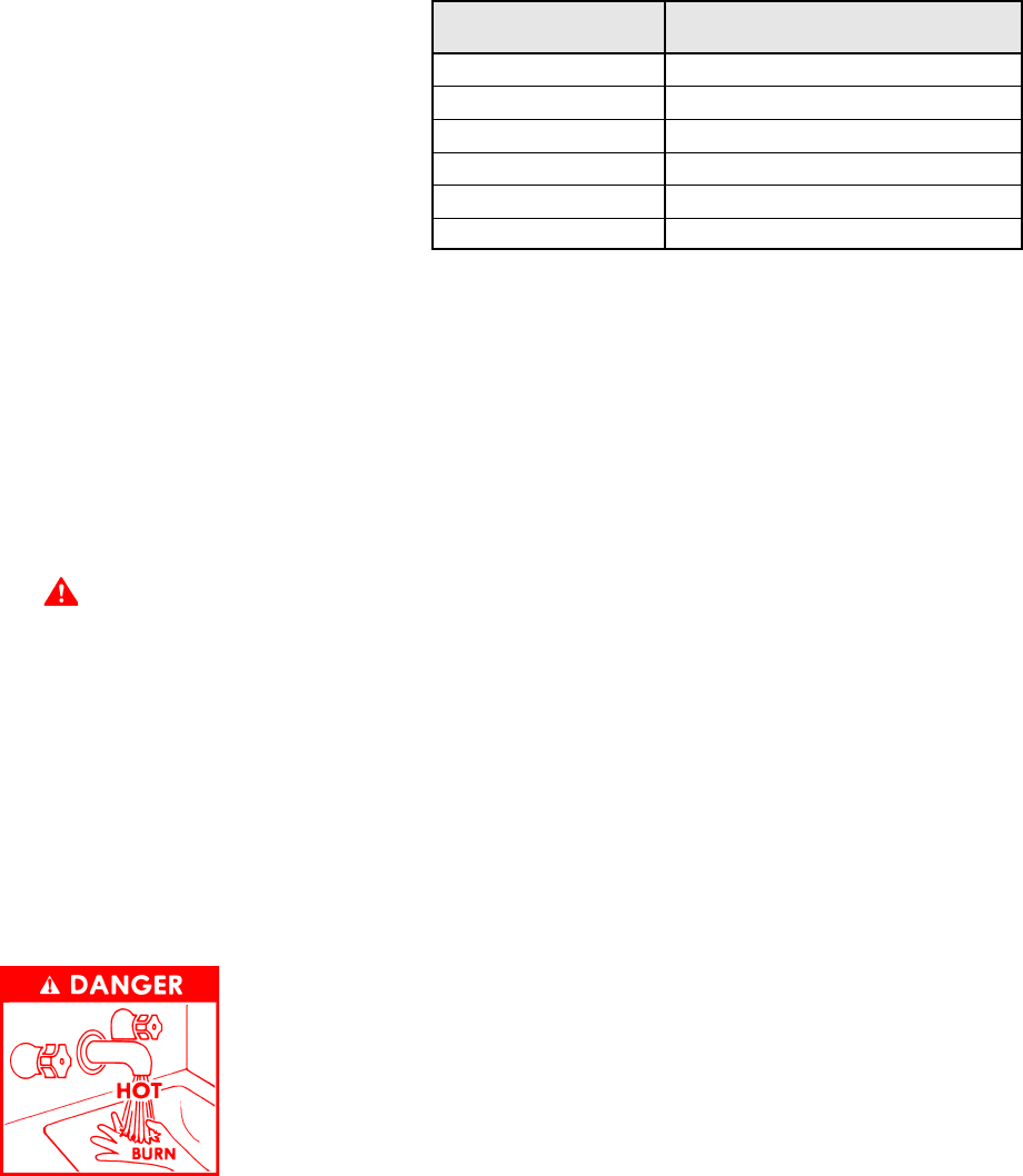
DANGER
HOT WATER TEMPERATURES REQUIRED FOR AUTOMATIC
DISHWASHER AND LAUNDRY USE CAN CAUSE SCALD
BURNS RESULTING IN SERIOUS PERSONAL INJURY AND/OR
DEATH. THE TEMPERATURE AT WHICH INJURY OCCURS VARIES
WITH THE PERSON'S AGE AND TIME OF EXPOSURE. THE
SLOWER RESPONSE TIME OF CHILDREN, AGED OR DISABLED
PERSONS INCREASES THE HAZARDS TO THEM. NEVER ALLOW
SMALL CHILDREN TO USE A HOT WATER TAP, OR TO DRAW
THEIR OWN BATH WATER. NEVER LEAVE A CHILD OR DISABLED
PERSON UNATTENDED IN A BATHTUB OR SHOWER.
THE WATER HEATER SHOULD BE LOCATED IN AN AREA WHERE
THE GENERAL PUBLIC DOES NOT HAVE ACCESS TO SET
TEMPERATURES.
IT IS RECOMMENDED IN DOMESTIC HOT WATER APPLICATIONS
THAT LOWER WATER TEMPERATURES BE USED TO AVOID THE
RISK OF SCALDING. IT IS FURTHER RECOMMENDED, IN ALL
CASES, THAT THE WATER TEMPERATURE BE SET FOR THE
LOWEST TEMPERATURE WHICH SATISFIES THE USER'S HOT
WATER NEEDS. THIS WILL ALSO PROVIDE THE MOST ENERGY
EFFICIENT OPERATION OF THE BOILER AND MINIMIZE SCALE
FORMATION IN THE HEAT EXCHANGER, THUS PROLONGING
THE LIFE OF THE BOILER.
SETTING THE WATER HEATER TEMPERATURE AT 120°F (49°C)
WILL REDUCE THE RISK OF SCALDS. SOME STATES REQUIRE
SETTINGS AT SPECIFIC LOWER TEMPERATURES. TABLE 20
ABOVE SHOWS THE APPROXIMATE TIME-TO-BURN
RELATIONSHIP FOR NORMAL ADULT SKIN.


