


page
2
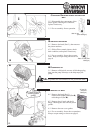
Inlet
LHS
RHS
INPUT WATER SUPPLY
Utilize liquids free from impurities (such as sand or other solid particles
which will affect the efficiency of the valves, the piston and the packings).
For this reason it is advisable to fit a filter on the suction hose, with a large
filtering surface and low load loss. Replace the filter as soon as it becomes
clogged up, to avoid noisy operation and pulsations which can damage the
mechanical parts of the pump. If the pump draws from a tank place the filter
at the entrance of the same.
NB: Maximum temperature of pumped liquid is 60°C (140°F),
maximum forced suction (measured at the pump) is
10 bar (145
PSI).
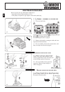
BEFORE STARTING UP
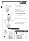
1. The pump is supplied complete with oil, so the first thing to do is remove
the red cap utilized for transportation, and insert the dipstick which is
supplied with the pump.
2. Check that oil is at the correct level, by means of the oil level window
topping up if necessary using oil type indicated in chart 1.1 page 8.
3. Make sure that inlet water flow is sufficient-at least the same value as the
pump flow and that it comes out without air bubbles.
4. Prime the pump with the outlet completely open.
5. Then start up the motor, if using a gas engine bring the RPM 's up to pre-
set level.
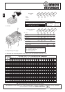
Fig.4b- Check the suction filter
periodically.
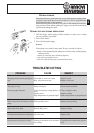
INSTALLATION
The pump must be installed horizontally, blocked in a stable manner, by
means of the coupling flanges suitable for the type of motor/engine with
which the pump will be driven. If pulley drive is used, you must have a
protection guard.
.The pumps can rotate either clockwise or anticlockwise.
Suction and outlet piping can be attached either to the left hand side or right
hand side of the pump.
The suction hose must:
- be of a diameter equal to from 1 to 1.5 times the suction part of the pump,
- set up in such a way as to avoid the forming of air pockets,
- be as short as possible and hermetically attached to the pump to avoid
sucking air.
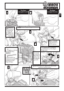
Below please find an example of a correct installation:
Fig.5b- Replace the
RED cap with the
dipstick supplied
with the pump.
Filter mod.FAS
COD.3000, max 20L/min
38 MESH
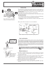
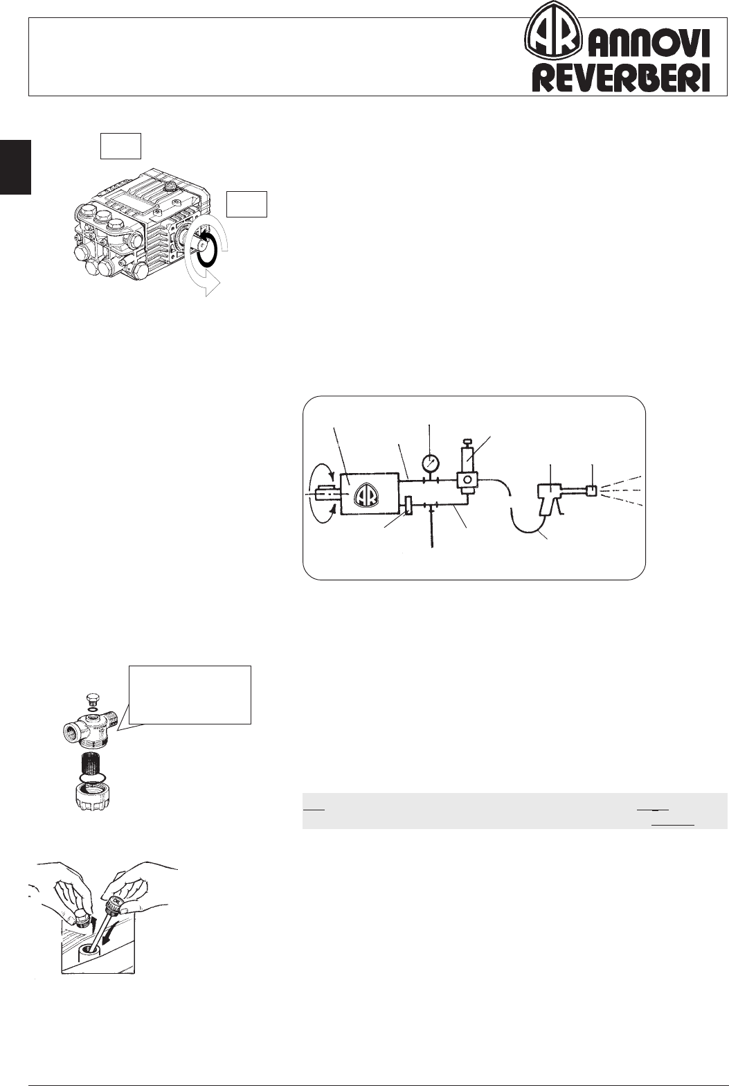
Fig.2b- Installation schematic with pressure regulating valve
OUTOUT
OUTOUT
OUT
Pump
Outlet
MINIMATIC / ZEROMATIC 83
GYMATIC / COMBISET
Gun Nozzle
By-pass
⇑
Filter
ININ
ININ
IN
O
➦
Outlet
Fig.1b- The pump can rotate either in
clockwise or anticlockwise direction.
Pressure
gauge
High pressure
hose
Inlet