


8
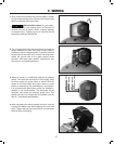
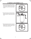
7. WIRING
LINE
LINE
MOTOR
MOTOR
BLACK
WHITE/STRIPE
BLUE
WHITE
TAB
TAB
SCREW
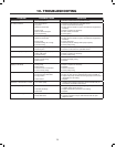
1. Shut off the circuit breaker for the well system. Loosen
the top screw housing cover. Flip the cover forward and
remove to expose the control wires.
Electrocution hazard. For your safety,
the information in this manual must be followed to
minimize the risk of electric shock, property damage
or personal injury. Properly ground to conform with all
governing codes and ordinances.
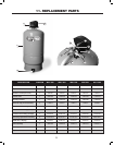
2. The 12 gauge wire leads are pre-stripped and ready to
accept standard wire nuts. Each wire is color coded to
correspond with the diagram below. Conduit knockouts
are provided at the back of the control mounting plate.
Attach the ground wire to the green ground screw
provided. Use water tight conduit, connections, and
wire nuts for an outside application.
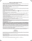
3. Wiring is similar to a traditional mechanical pressure
switch. Two leads are connected to line supply, while
the other supply the pump motor or starter. Wire the
control to the line supply and pump motor or pump
starter as required by the manufacturer's instructions.
It is recommended that service switch be installed in
addition to the circuit breaker. The disconnect for the
controller must break all incoming power lines. This
should interrupt line voltage and be installed near the
Well-X1
™
and labeled appropriately.
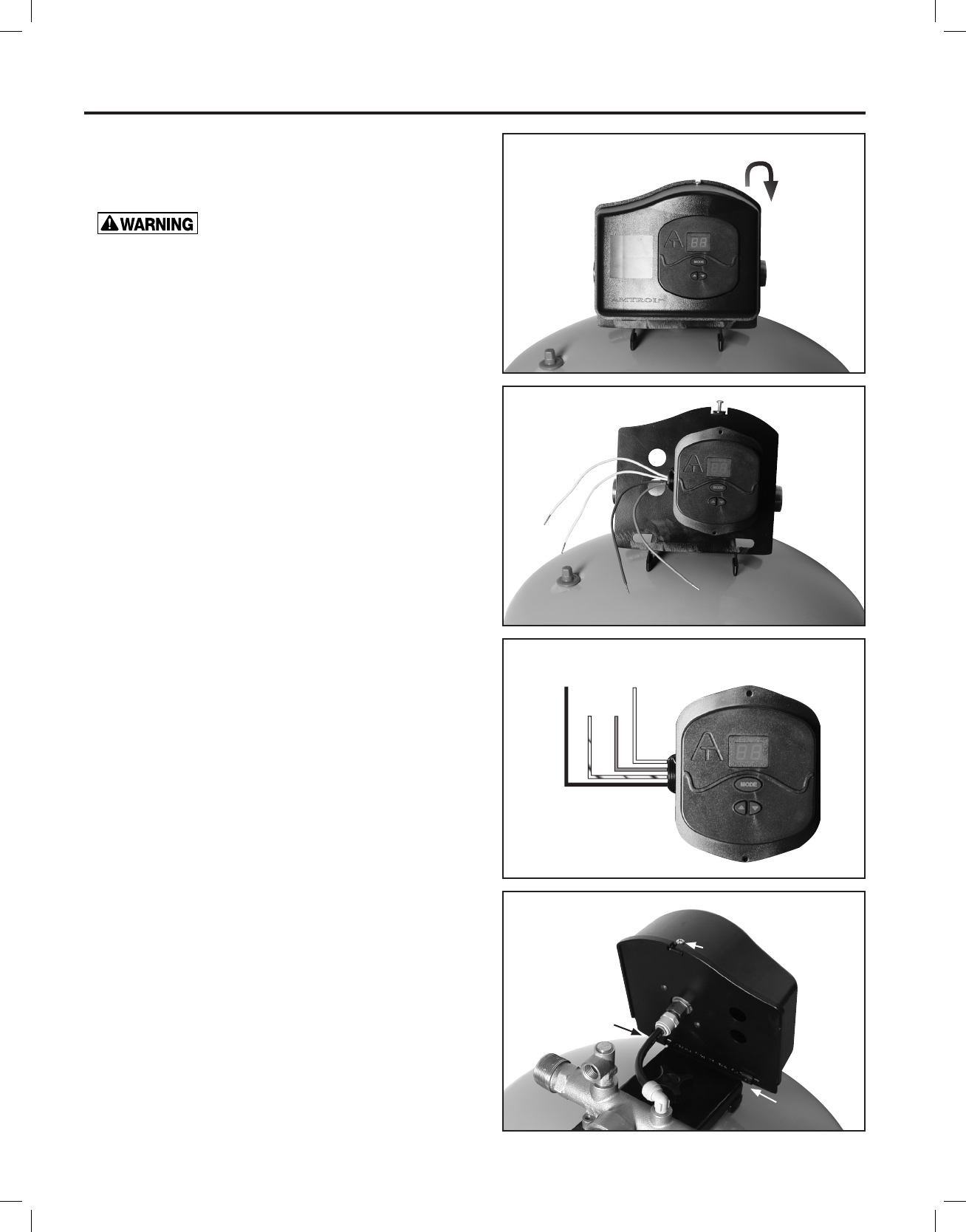
4. After completing the wiring, reattach the front cover by
inserting the plastic tabs and snapping the cover into
place. Tighten the top screw and ensure no loose wires
protrude from the housing.