


-7-
B. PIPING
PIPING SHOULD BE ACCOMPLISHED WITH UNIONS.
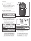
Step 1 - Locate the BOILER MATE™ near boiler.
Step 2 - Connect the cold water piping.
a. Shut off the cold water supply at the main shut-off
valve.
b. Drain existing domestic water system. Open 1 or
more system faucets to prevent vacuum.
c. When the system is drained, for boilers that have an
external or internal tankless heater, disconnect the
tankless heater from the domestic hot water piping.
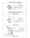
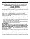
EXTERNAL TANKLESS HEATERS
Disconnect all the lines to the boiler and plug the boiler tap-
pings. Disconnect the external heater from the domestic sys-
tem piping and discard appropriately.
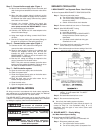
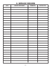
INTERNAL TANKLESS COILS
PREVENT PRESSURE BUILD-UP IN
ANY EXISTING INTERNAL TANK-
LESS COIL. Do not plug incoming or outgoing tappings in
the internal tankless coil plate. Leave the coil in the boiler
and leave system connections open, to prevent pressure
build-up. (Figure 3)
d.
Install a shut-off valve in the existing cold water line.
e. Run 3/4" or 1/2" tube and fittings from the city main,
as required, to the BOILER MATE™
f. If a backflow preventer, pressure reducing valve or
check valve is installed anywhere between the
BOILER MATE™ and the city main, install a properly
sized Therm-X-Trol
®
pre-pressurized diaphragm-type
thermal expansion tank. See the water supplier or
local plumbing inspector for more information
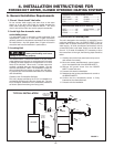
Step 3 - Connect domestic hot water piping Figure 5.
EXPLOSION HAZARD. THE
PRESSURE OF THE HEAT TRANSFER
MEDIUM MUST BE LIMITED TO A MAXIMUM OF 30 PSIG
BY AN APPROVED SAFETY OR RELIEF V
AL
VE ON YOUR
BOILER. THE TANK PRESSURE MUST BE LIMITED TO 150
PSIG MAXIMUM BY THE INSTALLATION OF A
TEMPERATURE AND PRESSURE RELIEF VALVE
(INCLUDED).
SCALDING HAZARD: A CHECK VALVE
MUST BE INSTALLED IN THE BOILER
RETURN LINE TO PREVENT GRA
VITY FLOW THROUGH
THE HEAT EXCHANGER. THIS CAN CAUSE OVER HEATING
AND RESUL
T IN SERIOUS SCALDING.
a.
Attach the blow-down tube from the T & P valve
outlet. Install the blow-down tube to within 6" of the
floor. The blow-down tube should be placed so that it
will discharge to a drain with adequate capacity. No
reducing couplings, valves, or any other type of
restriction is to be installed in this line. The blow-down
tube must be installed to allow free and complete
drainage of both the valve and the blow-down tube.
b. Install a union, shut-of
f valve and vacuum br
eaker on
the hot water outlet.
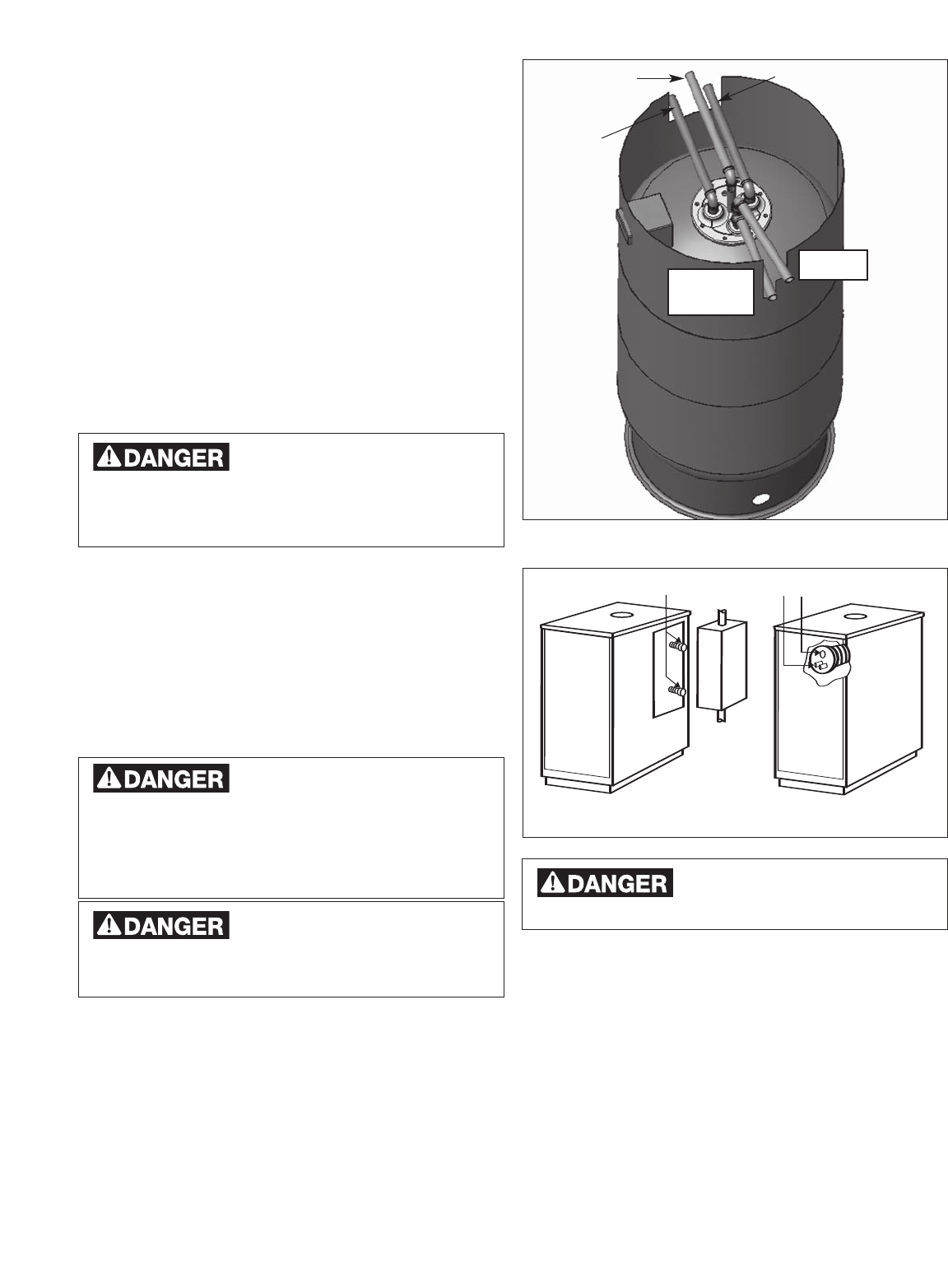
DAMAGE TO THE UNIT AND
LEAKAGE CAN OCCUR IF A
VACUUM BREAKER IS NOT INSTALLED.
c.
To minimize piping heat loss during non-draw periods,
a thermal trap can be installed in the hot water line as
shown in Figure 1.
Step 4 - Fill the BOILER MA
TE™.
a. Open a hot water faucet in the house to allow any air
in the BOILER MATE™ and in the piping to escape.
b. Open the shut-of
f valve in the cold water line.
c. Open the shut-of
f valve(s) in the hot water supply line.
d. When water dischar
ges fr
om the faucet, close it.
Check for system leaks and r
epair if necessary.
PLUG HERE
DO NO
T PLUG
INTERNAL
TA NKLESS
COILS
EXTERNAL
TA NKLESS
HEATER
X
FIGURE 3
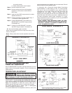
FIGURE 2
COLD
W
ATER
SUPPL
Y
T & P
OUTLET
BOILER
RETURN
BOILER SUPPL
Y
DOMESTIC
HOT W
ATER
OUTLET