


-6-
A. General Installation Requirements
1. Do not "short circuit" the boiler
Do not connect boiler supply and return lines to the same
section or in the same flow circuit in a boiler, because the
boiler water returning from the BOILER MATE™ will "short
circuit" and exit the boiler too cold for proper heat transfer.
2. Avoid high flow domestic water
recirculating loops
If a recirculating loop is necessary consult applicable Code
requirements. A flow of no more than 1/2 gpm is all that is
generally needed for temperature maintenance at the furthest
hot water fixture. Any flow greater than 1/2 gpm will result in
excessive heat loss and reduction in performance.
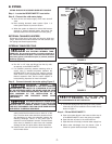
3. Locating Unit
The BOILER MATE™ should be located in an area where
water leakage from the tank or connections will not result
in damage to areas adjacent to the application or to lower
floors of the structure. When such a location cannot be
avoided, a suitable drain pan must be installed. The pan
must be connected to a drain. The installation location for
this unit should also be chosen to comply with the follow-
ing required and recommended dimensions for clearance
and accessibility:
Clearance from Combustible Surfaces
This unit is design certified by the C.S.A. for installation on
combustible flooring and in alcoves, closets, etc. The min-
imum clearance dimensions from combustible material is
as follows: (See dimensions given facing units)
Clearance From Combustible Surfaces
LEFT SIDE...........10" REAR.....................1"
RIGHT SIDE.........10" FLOOR ..................0"
TOP......................30" FRONT ..................1"
Recommended Clearance for Servicing
LEFT
....................10" HEAD ROOM ........30"
RIGHT
..................10" REAR.....................1"
FRONT
.................30"
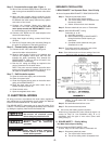
4. Instructions for reversing unit:
The unit is designed to be reversible, i.e. depending on the
particular installation area, the BOILER MATE™ can be
rotated 180° for easier connection to the boiler and cold
water supply. All units are shipped "left-handed" with all
connections (boiler, cold water supply) on the left side of
the unit. If, for ease of installation, it is necessary to have
the connections on the right, the following steps should be
taken:
1. Carefully remove the front panel (remove top screw
and unhook from stand).
2. Move the access panel/electronic control assem-
bly to the opposite side of the BOILER MATE™.
3. Remove the ground screw from the BOILER
MATE™ stand and save.
4. Proceed with electrical installation
5. Reassemble the access panel/electronic control to
the BOILER MATE™.
6. Confirm that the temperature sensor is firmly
inserted into the thermostat well.
7. Proceed with the installation.
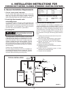
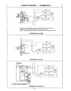
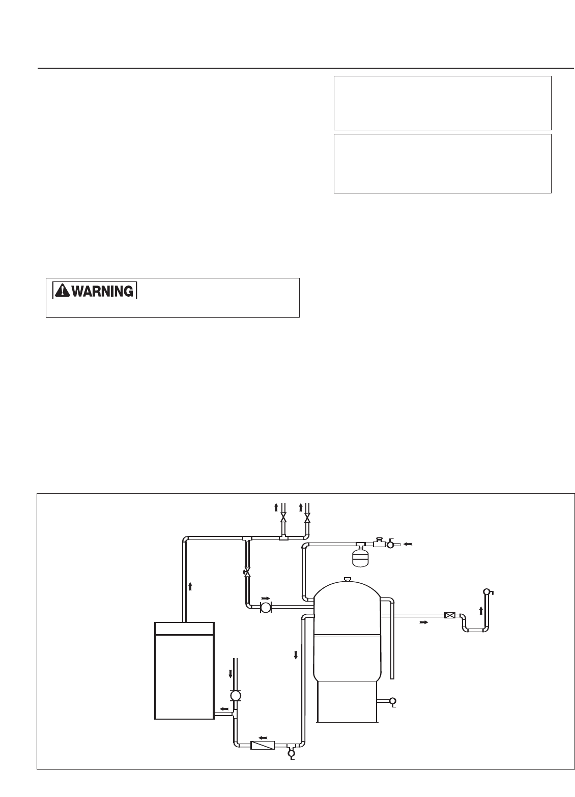
4. INSTALLATION INSTRUCTIONS FOR
FORCED HOT WATER, CLOSED HYDRONIC HEATING SYSTEMS
TYPICAL INSTALLATION
FIGURE 1
BOILER
HEATING ZONES
HEATING
SYSTEM
RETURN
ZONE VALVES
CONTROLLED BY
THERMOSTAT
HEATING
CIRCULATOR
CIRCULATOR
BOILER
MATE™
DRAIN
VAL VE
THERMAL
LOOP
DOMESTIC
HOT W ATE R
VAC UUM
BREAKER
DRAIN VAL VE
FLOW CHECK
VAL VE
THERM-X-TR OL
®
DOMESTIC
COLD WA TER
SUPPLY
PRV
SHUT-OFF
VAL VE
SHUT-OFF
VAL VE
SHUT-OFF
VAL VE
BOILER
SUPPLY
RELIEF VAL VE
BLOW -DOWN TUBE
BOILER
RETURN
Do not locate this product where
leaking and flooding could cause
damage to surrounding property.