


-6-
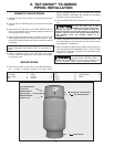
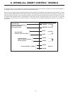
5. TOP DOWN™ TD-SERIES
PIPING INSTALLATION
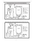
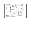
DOMESTIC WATER PIPING
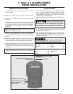
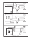
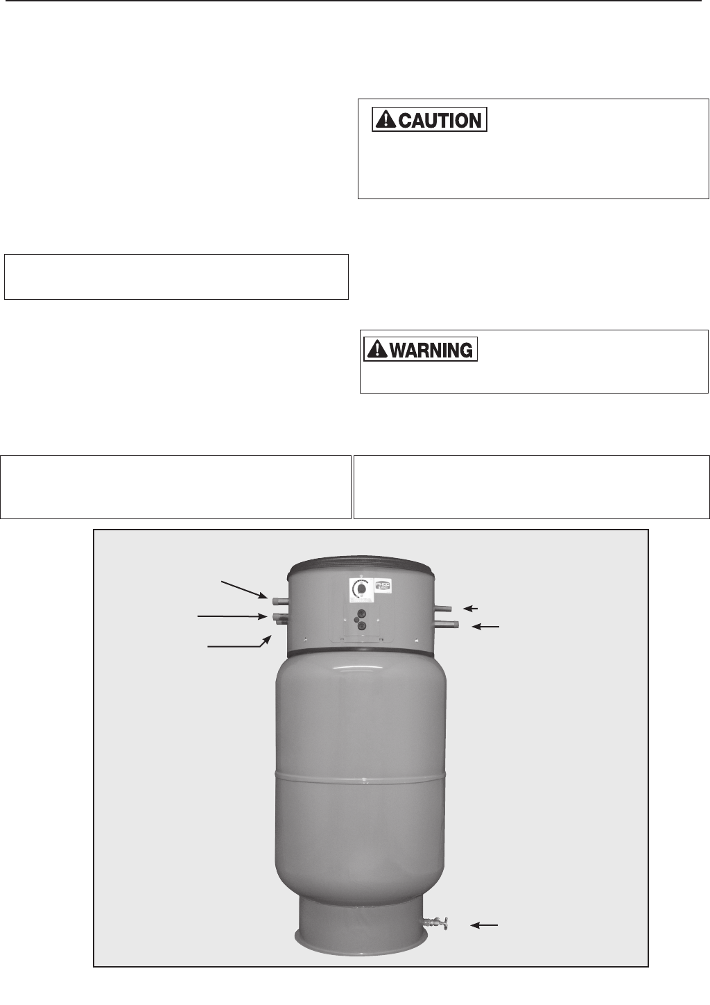
1. Connect the cold water supply to the pipe labeled COLD
WATER
2. Connect the HOT WATER piping to the domestic hot water
system.
3. Make an 8-inch “heat trap” on the HOT WATER outlet as
shown in the diagram. This will reduce standby losses from
heat migrating up the piping.
4. When all domestic water piping is complete, open the cold
water supply and allow some water to enter the tank. Look
and listen for signs of leaks and repair as necessary before
continuing.
Note: If installing on a city supply, ensure a dedicated
Thermal Expansion tank (Therm-X-Trol
®
or equivalent) is
used.
5. Install a blowdown tube on the T&P relief valve outlet.
Plumb to within 6 inches above a floor drain or as directed
by plumbing code.
BOILER PIPING
1. Plumb the circulator or zone valve on the BOILER SUPPLY
line. If using a separate circulator, the pump flange
can be mounted directly to the threaded pipe marked
BOILER SUPPLY. Alternately, the circulator can be placed
anywhere on the boiler supply line.
2. Pipe the BOILER RETURN connection to the boiler return
line.
Be sure the return line is NOT
plumbed to the suction side of any
heating circulators. This may require moving the
heating circulator off the boiler tapping on packaged
boilers. Failure to do so will result in overheating and
tank damage when the heating system is in
operation.
3. Install a weighted flow check on the boiler return line. This
is not necessary on systems utilizing a zone valve to control
the BoilerMate
®
temperature.
4. After completing the boiler piping, slowly open the boiler fill
valve and pressurize the BoilerMate
®
loop. Check for leaks
and repair as necessary. Proceed to the appropriate wiring
section in this manual.
If installing on city water supply a
properly sized THERM-X-TROL
®
is
required with the BoilerMate
®
and should be installed as set
forth in the THERM-X-TROL
®
product installation manual.
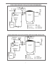
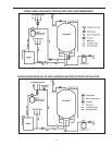
LEFT SIDE ............1”
RIGHT SIDE ...........1”
TOP .................9”
REAR ................1”
FLOOR ...............0”
FRONT ...............1”
Clearance From Combustible Surfaces
LEFT .................12”
RIGHT................12”
FRONT ...............30”
HEAD ROOM ..........9”
REAR ................1”
Recommended Clearance For Servicing
T&P RELIEF VALVE OUTLET
HOT WATER OUTLET
BOILER RETURN
(Bottom Left)
BOILER SUPPLY
(Bottom Right)
COLD WATER INLET
(Top Center)
DRAIN VALVE