


5
HIGH ALTITUDE INSTALLATIONS
WARNING
INSTALLATIONS ABOVE 2000 FEET (610 METERS) REQUIRE
REPLACEMENT OF THE BURNER ORIFICE IN ACCORDANCE
WITH SECTION 11.1.2 OF THE NATIONAL FUEL GAS CODE
(ANSI Z223.1). FAILURE TO REPLACE THE ORIFICE WILL
RESULT IN IMPROPER AND INEFFICIENT OPERATION OF THE
APPLIANCE RESULTING IN THE PRODUCTION OF
INCREASED LEVELS OF CARBON MONOXIDE GAS IN
EXCESS OF SAFE LIMITS WHICH COULD RESULT IN
SERIOUS PERSONAL INJURY OR DEATH.
You should contact your gas supplier for any specific changes
which may be required in your area.
As elevation above sea level is increased, there is less oxygen
per cubic foot of air. Therefore, the heater input rate should be
reduced at high altitudes for satisfactory operation with the reduced
oxygen supply. Failure to make this reduction would result in an
overfiring of the heater causing sooting, poor combustion and/or
unsatisfactory heater performance.
REQUIREMENTS
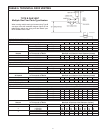
Ratings specified by manufacturers for most appliances apply for
elevations up to 2000 feet. For elevations above 2000 feet, ratings
must be reduced at the rate of 4% for each 1000 feet above sea
level. For example, if a heater is rated at 120,000 Btuh at sea
level, to rate the heater at 4000 feet, you subtract 4 (once for
each thousand feet) x.04 (4% input reduction) x 120,000 Btuh
(original rating) from the original rating. Therefore, to calculate
the input rating at 4,000 feet: 4 x .04 x 120,000 =19,200 Btuh,
120,000 - 19,200 = 100,800 Btuh. At 6000 feet the correct input
rating should be 91,200 Btuh.
The input reduction is primarily achieved by reducing the size of
the main burner orifices. To do this, the main burner orifices require
replacement with orifices sized for the particular installation
elevation. Correct orifice sizing and parts may be obtained from
A.O. Smith Water Products Company. When ordering, be sure
to state the model number and the altitude of the location where
the water heater is being installed.
Upon completion of derating of the heater, adjustment to the gas
pressure regulator may be required. See CHECKING THE INPUT
section in this manual for inlet and manifold pressure
requirements.
Also due to the input rating reduction required at high altitudes,
the output rating of the appliance is also reduced and should be
compensated for in the sizing of the equipment for application.
FEATURES
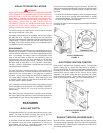
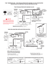
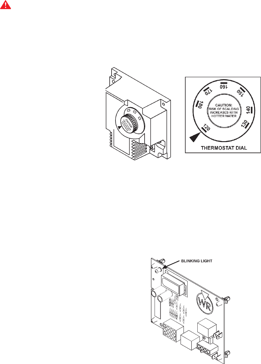
HIGH LIMIT SWITCH
The digital thermostat (Fig. 2) contains the high limit (energy cutoff)
sensor. The high limit switch interrupts main burner gas flow
should the water temperature reach 203°F (95°C).
In the event of high limit switch operation, the appliance cannot
be restarted unless the water temperature is reduced to
approximately 120°F (49°C). The high limit reset button on the
front of the control then needs to be depressed.
Continued manual resetting of high limit control, preceded by
higher than usual water temperature is evidence of high limit switch
operation. The following is a possible reason for high limit switch
operation:
• A malfunction in the thermostatic controls would allow the gas
valve to remain open causing water temperature to exceed
the thermostat setting. The water temperature would continue
to rise until high limit switch operation.
Contact your dealer or service agent if continued high limit switch
operation occurs.
DIGITAL THERMOSTAT
FIGURE 2
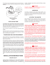
ELECTRONIC IGNITION CONTROL
Each heater is equipped with a ignition module. The solid sate
ignition control (Fig. 3), ignites the main burner by utilizing a
silicone nitride ignitor. The silicone nitride ignitor shuts off during
the heating cycle and the main burner flame is sensed through a
remote flame sensor integral to the silicone nitride ignitor
assembly. The ignition control will try to ignite the main burner
three times before lockout. Then it waits one hour before trying
again to ignite the main burners. This is a continuous cycle.
IGNITION CONTROL BOARD
FIGURE 3
EXHAUST INDUCER (BLOWER ASSY.)
All BCG low NOx models are equipped with an exhaust inducer.
The inducer assists in drawing in fresh air to the unit for combustion
and then assists in dispensing the combustion by-products into
the venting leading outside.