


10
WATER LINE CONNECTIONS
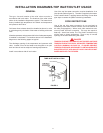
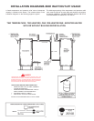
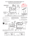
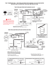
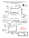
This manual provides detailed installation diagrams (see pages
13-19 of this manual) for typical methods of application for the
water heater(s).
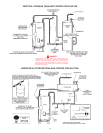
The water heater may be installed by itself, or with a separate
storage tank, on both single and two-temperature systems. When
used with a separate storage tank, the circulation may be either
by gravity or by means of a circulating pump. When a circulating
pump is used it is important to note that the flow rate should be
slow so that there will be a minimum of turbulence inside the
heater.
If a water heater is installed in a closed water system, provisions
for the thermal expansion in the Hot Water System must be
provided. Contact the water supplier or local plumbing inspector
on how to control this situation.
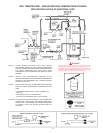
WATER (POTABLE) HEATING AND SPACE
HEATING (See pages 13-19)
1. All piping components connected to this unit for space heating
applications shall be suitable for use with potable water.
2. Toxic chemicals, such as those used for boiler treatment, shall
NEVER be introduced into this system.
3. This unit may NEVER be connected to any existing heating
system or component(s) previously used with a non-potable
water heating appliance.
4. When the system requires water for space heating at
temperatures higher than required for domestic water
purposes, a tempering valve must be installed. Please refer
to installation diagrams on pages 16 and 18 of this manual for
suggested piping arrangements.
CAUTION
A closed system will exist if a check valve (without bypass),
pressure reducing valve (without bypass), or a water meter (without
bypass) is installed in the cold water line between the water heater
and street main (or well).
Excessive pressure may develop in such closed systems,
causing premature tank failure or intermittent relief valve
operation.
This is not a warranty failure. An expansion tank or
a similar device may be required in the inlet supply line between
the appliance and the meter or valve to compensate for the
thermal expansion of the water.
SYSTEM CONNECTIONS
The system installation must conform to these instructions and to
the local code authority having jurisdiction. Good practice requires
that all heavy piping be supported.
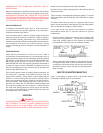
THERMOMETERS (Not Supplied)
Thermometers should be obtained and field installed as shown in
the installation diagrams.
Thermometers are installed in the system as a means of detecting
the temperature of the outlet water supply.
RELIEF VALVE
This water heater is equipped with a combination temperature-
pressure relief valve that complies with the standard for relief
valves for hot water supply system, ANSI Z21.22. FOR SAFE
OPERATION OF THE WATER HEATER, THE RELIEF VALVE(S)
MUST NOT BE REMOVED OR PLUGGED.
ASME ratings cover pressure relief capacities. CSA ratings cover
release rate with temperature actuation.
In addition to the appliance relief valve, each remote storage tank
which may be used in conjunction with this appliance shall also
be installed with a properly sized, rated and approved combination
temperature (ANSI) and pressure (ASME) relief valve(s).
WARNING
THE PURPOSE OF RELIEF VALVE IS TO AVOID EXCESSIVE
PRESSURE OR TEMPERATURE INTO THE STEAM RANGE,
WHICH MAY CAUSE SCALDING AT FIXTURES, TANK
EXPLOSION, SYSTEM OR HEATER DAMAGE. NO VALVE IS
TO BE PLACED BETWEEN THE RELIEF VALVE AND TANK.
Your local code authority may have other specific relief valve
requirements.
A DRAIN LINE MUST BE CONNECTED TO THE RELIEF VALVE
TO DIRECT DISCHARGE TO A SAFE LOCATION TO AVOID
SCALDING OR WATER DAMAGE. THIS LINE MUST NOT BE
REDUCED FROM THE SIZE OF THE VALVE OUTLET AND MUST
NOT CONTAIN VALVES, RESTRICTIONS NOR SHOULD IT BE
LOCATED IN FREEZING AREAS. DO NOT THREAD OR CAP
THE END OF THIS LINE. RESTRICTED OR BLOCKED
DISCHARGE WILL DEFEAT THE PURPOSE OF THE VALVE
AND IS UNSAFE. DISCHARGE LINE SHALL BE INSTALLED
TO ALLOW COMPLETE DRAINAGE OF BOTH THE VALVE AND
LINE.
See SERVICE INFORMATION section for procedure and
precautions.