


4
3
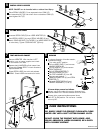
INSTALL HANDLES
1
3
2
FERRULE
COUPLING NUT
MAKE WATER SUPPLY CONNECTIONS
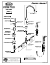
Connect water supply to FAUCET (1) with 1/2" IPS FLEXIBLE SUPPLIES (3)
or 3/8"O.D. BULL-NOSE RISERS (2). Use adjustable wrench to tighten
connections. Do not over tighten.
Be careful not to kink copper supply when bending. Use tubing cutter to
cut to proper length.
2
2
1
3
4
5
7
6
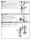
INSTALL
VALVE BODIES
Install LOCK NUT (1) and RUBBER WASHER (2) onto VALVE BODIES (3).
Insert VALVE BODY (3) through mounting hole from underside of SINK.
Set VALVE BODIES (3), so that their outlets are facing toward center
of sink, and tighten LOCK NUT (1) using WRENCH (8)
supplied with faucet.
Insert SEAL WASHERS (6) into SPOUT BODY SUPPLY HOSES (7). Loop
SUPPLY HOSES (7) if required and tighten connection to VALVE BODIES (3).
Place RUBBER RING (4) into DECK ADAPTER (5) and thread DECK
ADAPTER (5) onto VALVE BODY (3) until snug against internal stop.
NOTE: FLEXIBLE SUPPLIES OR BULL-NOSE RISERS MUST BE PURCHASED SEPARATELY.
Push INDEX CAP (6) in hole of HANDLE (4).
Secure HANDLE (4) with HANDLE SCREW (5).
Find correct position of HANDLE (4) by adjusting male teeth on
ADAPTER (1) to female teeth in HANDLE (4) and push HANDLE (4)
onto ADAPTER (1).
Thread HANDLE BASE (3) onto DECK ADAPTER (7)
Push ADAPTER (1) on VALVE STEM (2), so that the hole of the
ADAPTER (1) without spline is facing up. See figure "A".
8
TOP
Figure "A"
SPLINE END DOWN
M968412A
6
5
4
3
1
7
2