


Installation Instructions
Fig. 5
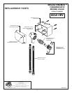
1. Remove the bottom SUPPLY HOSE (1) from the
SELECTRONIC ENCLOSURE (2). Fig. 3
2. Remove BOTTOM PLUG (3) from SELECTRONIC
ENCLOSURE (2). Fig. 3
3. Remove 4 screws from MIXER ENCLOSURE
COVER (2) and pull off COVER (2). Fig. 3b
4. Remove MIXING VALVE (7) from ENCLOSURE (3).
5. Install MIXER ENCLOSURE (4) under SELECTRONIC
ENCLOSURE (2) as shown in Fig. (3a). Hold the MIXER
ENCLOSURE (4) in that location and mark the four
mounting hole locations as shown. Fig. (3a)
NOTE: MIXER ENCLOSURE SUPPLY HOSES are
20" long. Distance between wall valves and MIXER
ENCLOSURE (4) must be taken into consideration.
5. The ENCLOSURE (4) works best if secured to a wall
stud or cross brace within the wall, using the SCREWS
(5) supplied. If the MIXER ENCLOSURE (4) is to be
installed on a tile or plaster wall the ANCHORS (6) and
SCREWS (5) should be used.
6. For installations on drywall or tiled walls; use
ANCHORS (6) and SCREWS (5) for securing MIXER
ENCLOSURE (4) to finished wall. Drill four 1/4" dia.
holes a minimum of 1-3/4" deep. Insert the four
ANCHORS (6) flush with face of the finished wall.
Align the MIXER ENCLOSURE (4) and Install the
MOUNTING SCREWS (5). Tighten to secure MIXER
ENCLOSURE (4) to mounting surface.
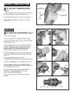
1. Install MIXING VALVE (1) back into ENCLOSURE.
2. Install FIBER SEAL WASHER (4) on MIXING
VALVE NIPPLE (3). Hold MIXING VALVE (1) in place
with one hand and with your other hand thread
SWIVEL NUT (2) onto MIXING VALVE NIPPLE (3).
Fig. 4. Use an adjustable wrench to tighten SWIVEL
NUT (2). Fig. 4a
3. Replace ENCLOSURE COVER and tighten securely.
1. Turn off hot and cold water supplies before
beginning.
2. Connect FLEXIBLE SUPPLIES (1, 2) directly to wall
supplies. Connection on MIXER supplies are 3/8"
compression. Connect left supply to Hot and right
supply to Cold wall supply. Use adjustable wrench to
tighten connections. Do not over tighten. FIG. 5
3. Faucet supplies measure 20" from the bottom of the
ENCLOSURE (3) base.
Note: If additional supply length is required, installer
must purchase parts separately.
Important: If SUPPLY HOSES (1, 2) are too long, loop
as to avoid kinking.
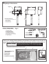
MOUNT ENCLOSURE; Fig. 3
1
CONNECT MIXING VALVE; Fig. 4
2
CONNECT MIXING VALVE TO
WATER SUPPLIES; Fig. 5
3
2
Fig. 4 Fig. 4a
1
2
3
4
3
1
HOT COLD
2
2
ADJUSTABLE
WRENCH
WALL SUPPLIES
INSTALLATION
Fig. 3
Fig. 3a
Fig. 3b
4-1/4"
(108mm)
1-3/16"
(46mm)
4
2
MOUNTING HOLES
ILLUSTRATION SHOWN
LESS MIXING VALVE
1
3
SUPPLIES
WASTE
LAVATORY RIM OR
MOUNTING SURFACE
ENCLOSURE
MOUNTING
HOLES
2
6
4
5
7
Fig. 7d
Fig. 7a
Fig. 7e
Installation Instructions