


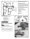
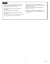
Fig. 2
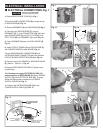
1. Determine location of ENCLOSURE (1). It must be
located with-in the 14" (356mm) by 21" (533mm)
shaded area shown in Figure 2 in order for electrical
connections from the spout assembly to be made.
NOTE: ENCLOSURE SUPPLY HOSE is 20". Distance
between wall supply and ENCLOSURE (1) must be
taken into consideration.
2. Remove 4 screws from COVER (2) and pull off
COVER (2). Hold the ENCLOSURE (1) in desired
location and mark the four mounting hole locations as
shown. Fig. 2.
3. The ENCLOSURE (1) works best if secured to a wall
stud or cross brace within the wall, using the SCREWS
(3) supplied. If the ENCLOSURE (1) is to be installed on
a tile or plaster wall the ANCHORS (4) and SCREWS
(3) should be used.
4. For installations on drywall or tiled walls; use
ANCHORS (4) and SCREWS (3) for securing
ENCLOSURE (1) to finished wall. Drill four 1/4" dia.
holes a minimum of 1-3/4" deep. Insert the four
ANCHORS (4) flush with face of the finished wall.
Align the ENCLOSURE (1) and Install the MOUNTING
SCREWS (3). Tighten to secure ENCLOSURE (1) to
mounting surface.
14"
(356mm)
3-3/4"
(96mm)
2-3/4"
(71mm)
3"
(76mm)
21"
(mm)
2
4
3
1
1
1
20"
(500mm)
MOUNTING HOLES
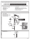
SUPPLIES
WASTE
ENCLOSURE
MOUNTING
HOLES
LAVATORY RIM OR
MOUNTING SURFACE
3
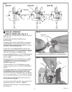
NOTE: If using Mixing Valve (optional) See Sheet
#M968808 for installation instructions.
MOUNT ENCLOSURE; Fig. 2
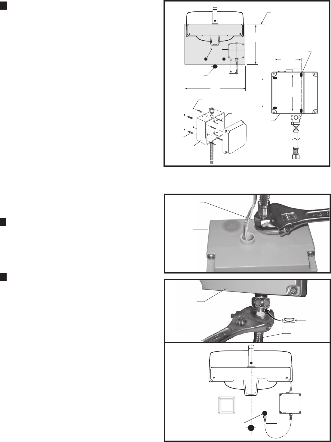
2
1. Connect SUPPLY NUT (1) from spout assembly to
nipple on top of ENCLOSURE (2). Tighten with
adjustable wrench to make a water tight connection.
Fig. 3.
NOTE; If using the optional Mixing Valve See Sheet
#M968808 for installation instructions.
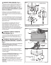
CONNECT SPOUT HOSE TO
ENCLOSURE; Fig. 3
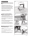
CONNECT WATER SUPPLY TO
ENCLOSURE AND WALL SUPPLY;
Fig. 4
3
Fig. 3
4
1
2
1
3
3
Fig. 4
2
1. Insert FIBER WASHER (4) into SUPPLY NUT (1) on
ENCLOSURE (2).
2. Connect SUPPLY NUT (1) on ENCLOSURE (2) to
FLEXIBLE SUPPLY HOSE (3). Tighten to make a
water tight connection. Use two wrenches to tighten if
necessary. Fig. 4.
3. Connect FLEXIBLE SUPPLY (3) directly to wall supply.
Connection on FLEXIBLE SUPPLY (3) is 3/8"
compression. Use adjustable wrench to tighten
connection. Do not over tighten. Fig. 4a.
Note: FLEXIBLE SUPPLY (3) measures 20" from the
bottom of the ENCLOSURE (1) base. If additional
supply length is required, installer must purchase parts
separately.
Important: If FLEXIBLE SUPPLY (3) is too long, loop to
avoid kinking.
COLD WATER OR
TEMPERED
WALL SUPPLY
4
Fig. 4a
DO NOT USE PIPE
SEALANT ON THREADS
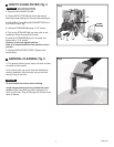
M965274
4" ELECTRICAL BOX
OR EQUIVALENT BY
OTHERS