


2
M968637 Rev 1.3
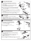
INSTALL LOWER SUPPORT BRACKET
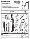
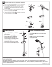
INSTALL SLIDE BAR
LOCATE UPPER MOUNTING BRACKET
INSTALL UPPER MOUNTING BRACKET
The SLIDE BAR works best when secured to the wall studs or
cross brace using the WOOD SCREWS. If a mounting into the
studs is not possible, use appropriate wall fasteners to provide
secure installation.
Mark a vertical center line in the location you wish to install the
SLIDE BAR. NOTE: The height from the finished floor is optional.
See rough-in drawing for suggested dimensions.
Determine desired height from the finished floor to the lower support
and mark a horizontal center line. Place the MOUNTING BRACKET (1)
on the center lines, with a pencil mark the location on the mounting
holes to be drilled. Fig. A.
Using 15/64" diameter drill. Drill two mounting holes 1" max. deep. Fig. B.
Install the bottom of SLIDE BAR (3) into the MOUNTING BRACKET (2).
IMPORTANT: The slot at the bottom of the slide bar must face toward the
wall. Rotate the slide bar until it locks into place and cannot be turned. Fig. B.
Install the two ANCHORS (2) provided into the mounting holes. (Use a hammer
to lightly tap ANCHORS (2) into place.) Make sure they are installed flush with
the finished wall.
Place the MOUNTING BRACKET (1) over the ANCHORS (2) and secure the
MOUNTING BRACKET (1) with the SCREWS (3) provided. Fig. C.
3
Slide the COVER (1) onto the MOUNTING BRACKET (2) flush
against the wall. Fig. A.
Install the upper MOUNTING BRACKET (1) onto the
SLIDE BAR (2). Align the MOUNTING BRACKET (1)
with center lines and mark the center mounting hole
with a pencil as shown. Fig. A.
Remove the SLIDE BAR (2) and set a side.
Using 15/64" diameter drill bit, drill mounting hole
1" max. deep. Fig. B.
Slide the COVER (4) onto the MOUNTING BRACKET (2) flush against the wall.
Install the ANCHOR (1) provided into the mounting hole. Make sure
it is installed flush with the finished wall. (Use a hammer to lightly tap
ANCHOR (1) into place.)
Place the MOUNTING BRACKET (2) over the ANCHOR (1) and secure
the MOUNTING BRACKET (2) with the SCREW (3) provided.
NOTE: Do not tighten fully.
Slide the MOUNTING BRACKET (2) up against the bottom of the mounting slot..
4
5
OPTIONAL
TO FINISHED
FLOOR
FINISHED
FLOOR
SLOT
BOTTOM OF MOUNTING SLOT
VERTICAL
C/L
HORZ.
C/L
Fig. A
Fig. B
Fig. C
3
3
2
1
1
2
2
2
2
2
1
1
3
4
1
Fig. B
Fig. B
Fig. B
Fig. A
Fig. A
Fig. A