


7
Vent Pipe Material
The following plastic materials may be used for both the
combustion air inlet and exhaust outlet piping subject to
state and local codes:
• Schedule 40 PVC or ABS
• Schedule 40 or 80 CPVC
• DWV Pipe is acceptable
Note: Use only solid (not foam core) piping.
Plastic pipe and fittings are available through most plumb-
ing suppliers. Always check the marking on the pipe to
make sure you are using the correct material.
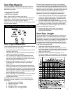
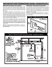
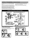
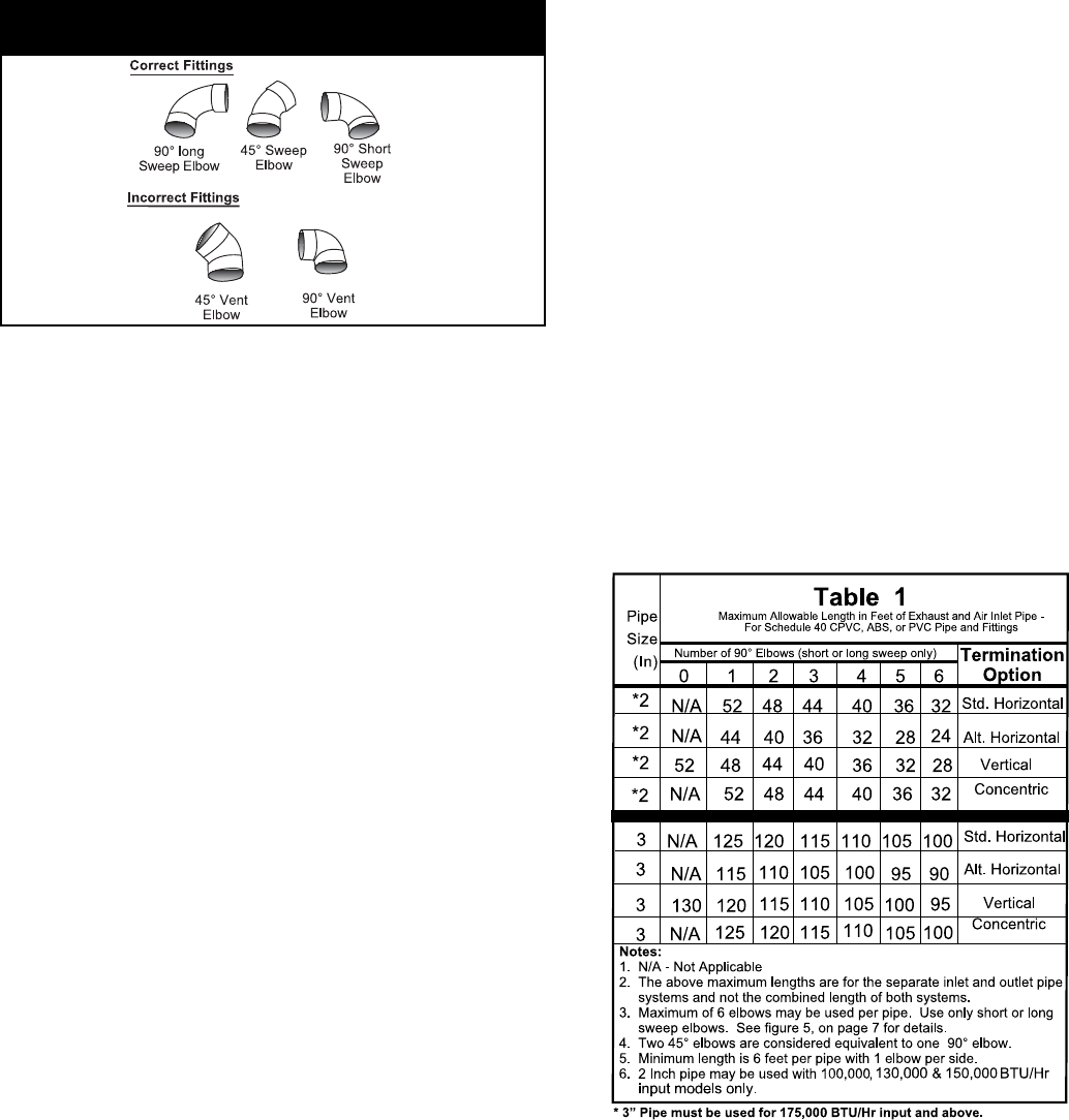
Important: Do not use vent elbows in this vent pipe installa-
tion (see figure 5 below).
Vent Pipe Installation
The following guidelines should be followed when installing
the air inlet and exhaust outlet piping:
• Venting should be as direct as possible with a minimum
number of pipe fittings.
• Vent diameter must not be reduced unless specifically
noted in the installation instructions.
• All 2” horizontal vent piping must be sloped upward
1/4 inch per foot (3” Piping must slope upward at 1/8”
per foot) so that condensate will run back to the heater
and exit through the condensate trap.
• Support all horizontal pipe runs every four feet and
all vertical pipe runs every six feet or according to
local codes.
• Vents run through unconditioned spaces where below
freezing temperatures are expected should be properly
insulated to prevent freezing. For horizontal runs, wrap
the vent pipe with nationally recognized/listed heat tape
and/or approved insulation for freeze protection. Install
per the manufacturer’s instructions.
• An air intake filter is included with the unit and must be
installed according to the installation instructions
supplied with the filter.
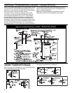
The combustion air inlet and exhaust outlet piping and
termination may be installed in one of the following type
terminations:
1. Standard Horizontal (2 Pipe)
2. Alternate Horizontal (2 Pipe)
3. Vertical (2 Pipe)
4. Concentric Vent - Through the Wall
5. Concentric Vent - Through the Roof
All pipe, fittings, pipe cement, primers and procedures
must conform to American National Standard Institute and
American Society for Testing and Materials (ANSI/ASTM)
standards in the United States. This water heater has been
design certified by the Canadian Standards Association for
use with the specified (CSA) listed plastic vent pipe.
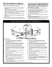
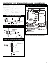
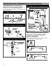
All joints in the inlet and outlet piping must be properly
cemented. Size and cut all piping before cementing.
1. Cut the pipe end square and remove all ragged edges
and burrs. Make sure the inside of the pipe is clean
and free of cuttings and loose dirt. Chamfer the end
and apply primer to the fitting and pipe.
2. Using a suitable grade of pipe cement, apply a moder-
ate, even coat inside the fitting. Apply a liberal amount
of cement to the outside of the pipe to socket depth.
Note: It is important to select the proper pipe cement for
the type of plastic pipe being used.
3. Assemble the parts quickly while the cement is
still wet. Twist the pipe 1/4 turn during insertion
and hold for 30 seconds.
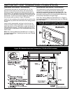
Vent Pipe Length
Size the exhaust outlet and combustion air inlet pipes as
specified in Table 1. This table lists the maximum allow-
able length in feet of the exhaust outlet and combustion air
inlet pipes as related to the number of required elbows and
the termination. The specified maximum lengths are for
the separate inlet and exhaust pipe systems and not the
combined length of both systems. Minimum pipe length is
6 feet with one elbow per side.
1. Determine termination type and pipe size.
2. Determine number of elbows in exhaust pipe. Do not
include the elbows in the termination or the condensate
trap. Corresponding number Indicates the maximum
length of exhaust pipe.
3. Determine number of elbows in inlet pipe. Do not
include the elbows in the termination. The correspond-
ing number indicates the maximum length of inlet pipe.
Figure 5: Correct and Incorrect Pipe Fittings